
EXPERIMENTING on living organisms is exciting and -as history shows- often rewarding. But there just aren't many people, dogs, birds, fish, etc., that you can (or would want to) subject to tests to determine such things as emotional reactions, nervous response, or sensorial perception. So, how about plants? They are after all, living things, and there are many indictations that when stimulated, they have sensitive, sensible reactions which can be measured on ordinary electronic equipment. Before going into the details of the equipment (which you can build yourself), let's get to know a little more about plants and how they tick.
Do They Just Sit? On first thought, plants appear to be quite remote from life as we know it. Their sedentary existence stands in strong contrast to energetic animals, which are endowed with a massive inventory of sensory capacities, fast reflex movements, and many active organs.
However, recent research has revealed that many of the same environmental factors and stimulations that affect animals also affect plants. of course, here we find modified abilities to sense, feel, and react. also, since a plant cannot run away from a threat to its existence, it would appear that special internal forces are set in motion to protect the organism from shock and possible death. These phenomena are akin to states of anxiety in animals and are evidenced by changes in the plant's psychogalvanic or electric states which occur in threatening situations. The recently discovered "Backster Effect" seems to provide evidence that plants have some ability to function in a mode of supersensory perception. This, of course, invites a host of exciting and unique investigations.
However, prior to engaging in plant-oriented experiments, you should realize that living systems frequently produce maverick results. While a plant may be regarded as an organic semiconductor having variable resistance and self-generating properties, it also has elements of apparent cellular consciousness. Electronic and mechanical response profiles are not uniform.
Some plants (such as the Mimosa Pudica) react rapidly; others give no discernible reactions to stimuli and still others exhibit strangely delayed responses. Remember that typical electrical signals provided by plants are in the low millivolt/microampere range. The equipment described here for making experiments should give you a good start, but for some extremely sensitive tests, you should avail yourself of an ultra-high-gain electrometer with input impedances of 1010 ohms or higher.
TRANSMITTER EFFECT
The behavior of plants in strong r-f fields has been studied only superficially. Although excessive energy levels induce heating and death and although plants are (electrically speaking) DC-oriented organisms, they nevertheless incorporate mechanisms which allow them to survive in the immediate vicinity of high-power radio transmitters of all types. To our knowledge, no tests have been performed to detect psychogalvanic behavior in plants under these conditions.
Another factor to remember is the importance of repetition. If, for example, a plant specimen is stimulated continuously, badly injured by burns or cuts, infrequently watered, etc., it is bound to tire quickly, perhaps lapse into shock and die. Terminal conditions are indicated by wilting, and discoloration usually forecasts death. Depending on the plant's overall chemistry and the amount of moisture retained in leaves and stem structures, a dead specimen is little else than a simple conductor of the carbon type and no psychogalvanic response of any kind should be expected. In short, be gentle and allow your plants to recuperate after they have served your purpose.
Some 350,000 plant species are known to science. At this time, we have no concise information as to which group is psychogalvanically superior to others. In general, however, it has been discovered (Lund, 1931) that the distribution of gradients of electrical potentials in large plants (such as trees) is more complex than in small plants. Apparently, each individual cell in a plant is electrically polarized and acts as a tiny, variable battery. The electrical potentials occurring in tissues are summation effects of the potentials of individual cells which may net either in series or in parallel (Rosene, 1935). Various mechanisms of correlation are involved here; but, as you are bound to discover, there is no complete uniformity from one specimen to the next, either in looks or reactions.
- B1-B3 — 9-volt battery
- B4 — 1.5-volt D battery
- BP1-BP6 — Five-way binding post
- C1 — 0.047-μF capacitor
- C2 — 200-pF capacitor
- C3 — 0.005-μF capacitor
- C4 — 0.01-μF capacitor
- C5,C6 — 50-μF, 10-volt electrolytic capacitor
- D1,D2 — Silicon diode (RCA SK-3016)
- I1 — 2.2-volt lamp (222)
- IC1 — Op amp IC (Fairchild μA741C)
- M1 — 1-mA DC meter (Calectro D1-912 or similar)
- Q1 — Transistor (RCA SK3011)
- Q2 — Transistor (RCA SK3003)
- R1 — 75,000-ohm resistor (see text)
- R2 — 100,000-ohm linear potentiometer (see text)
- R3 — 10,000-ohm linear potentiometer
- R4 — 100,000-ohm resistor
- R5,R6,R15 — 1000-ohm resistor
- R7 — 240,000-ohm resistor
- R8 — 1-megohm linear potentiometer
- R9 — 82-ohm resistor
- R10,R11 — 470,000-ohm resistor
- R12 — 3000-ohm resistor
- R13 — 10,000-ohm resistor
- R14 — 470,000-ohm resistor
- R16,R19,R20 — 100-ohm resistor
- R17 — 3.5-ohm, 1-watt resistor
- R18 — 10-ohm resistor
- R21 — 8-ohm potentiometer L pad
- S1,S3,S5 — Spst switch
- S2,S6 — Dpdt switch
- S4 — Dpst switch
- S7,S8 — Normally open pushbutton switch
- T1 — Audio transformer; 250/8-ohm, 200-mW (Calectro D1-726 or similar)
- Misc. — Suitable chassis and cabinet, battery holders, pilot-lamp mounting assembly, clamp support, machine clamp, clamp insulators, metal electrodes, twin shielded lead, rubber feet, plastic pot for plant, knobs, mounting hardware, etc.
- Note— The μA741C op amp is available from Polypaks, PO Box 942W, Lynnfield, MA, for $2.98.
PARTS LIST
MAGNETO-TROPICISM
This phenomenon was discovered by Dr. L. J. Audus, of Bedford College, London, in 1959, and reported by him in "Nature" in 1960. This report clearly showed that plants are highly susceptible to electromagnetic fields.
In tests, a viable seed of any plant is inserted in a small plastic container which is then placed between the poles of a strong magnet (of the magnetron type). For control purposes, another similar seed and container are placed far away from the magnet but with all other conditions being the same.
The "magnetized" seedling should show some bending effects plus a more emphatic growth than the control specimen.
It is also possible to "quick-ripen" fruit with a 900-gauss magnet. For example, a number of tomatoes placed at various distances around the magnet poles (anywhere from 3 to 17 inches away) will show varying rates of ripening. Those closest to the magnet will be the first to turn red. Horticulturists at the University of Utah believe that the earth's magnetic field activates an enzyme system inside the fruits and vegetables causing them to ripen and that a similar thing is caused artificially when the fruit is placed near a power magnet.
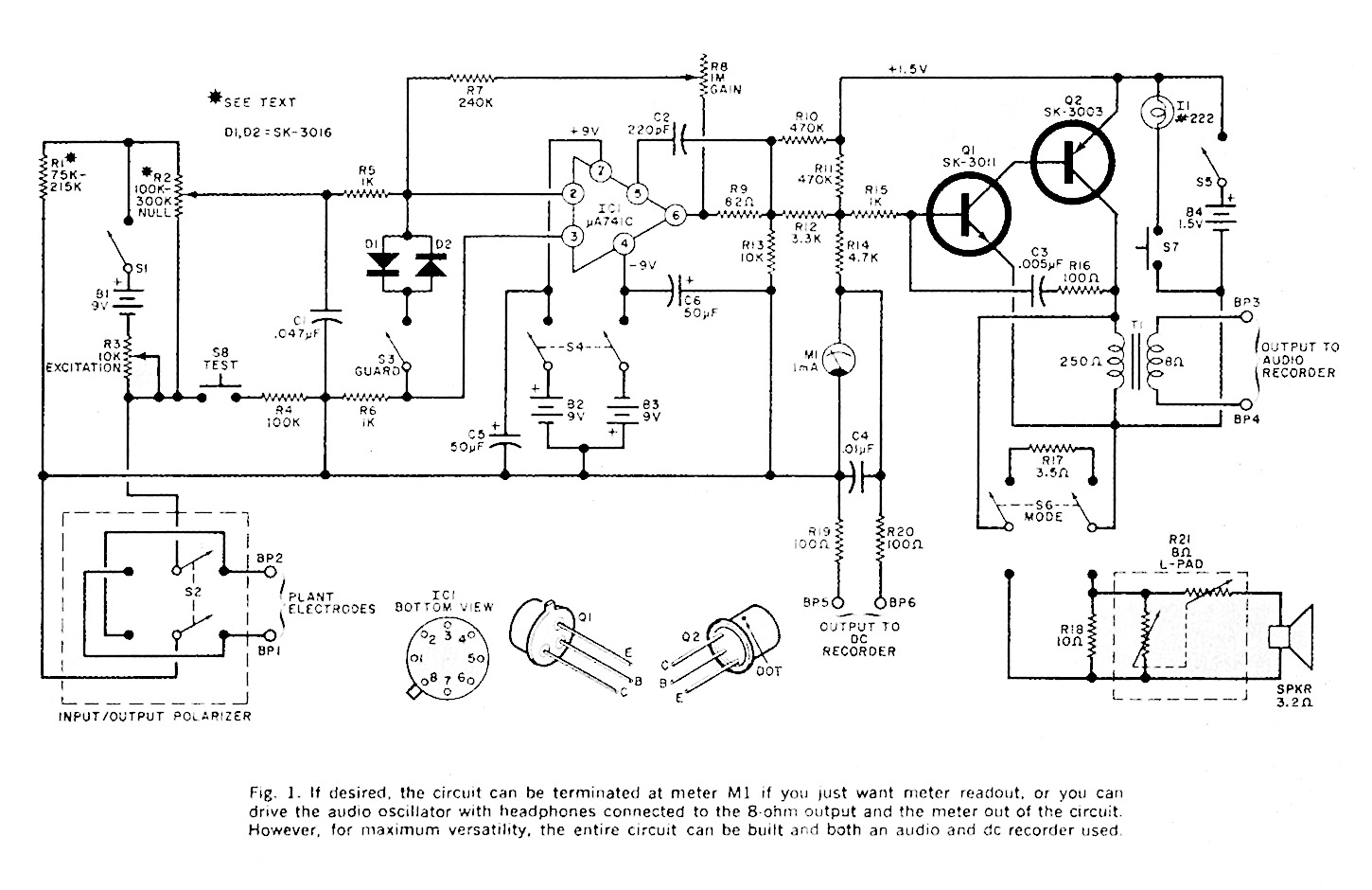
Plant Response Detector. The basic instrument for plant experiment is a response detector whose schematic is shown in Fig. 1. The detector has both visual (meter) and acoustical (speaker) indications of plant reaction. The audio tone output can also be connected to a conventional audio tape recorder and a pen-type recorder can be connected to the DE amplifier output to make permanent records of results.
The schematic is divided into four operational sections: the Wheatstone bridge input with exciter and input-output polarizer; an op amp guard circuit having a disabling feature; a high-gain DE operational amplifier; and an audio tone generator whose frequency varies with the potential generated in the plant. The op amp used has a large-signal gain of 100,000 and has built-in short circuit protection.
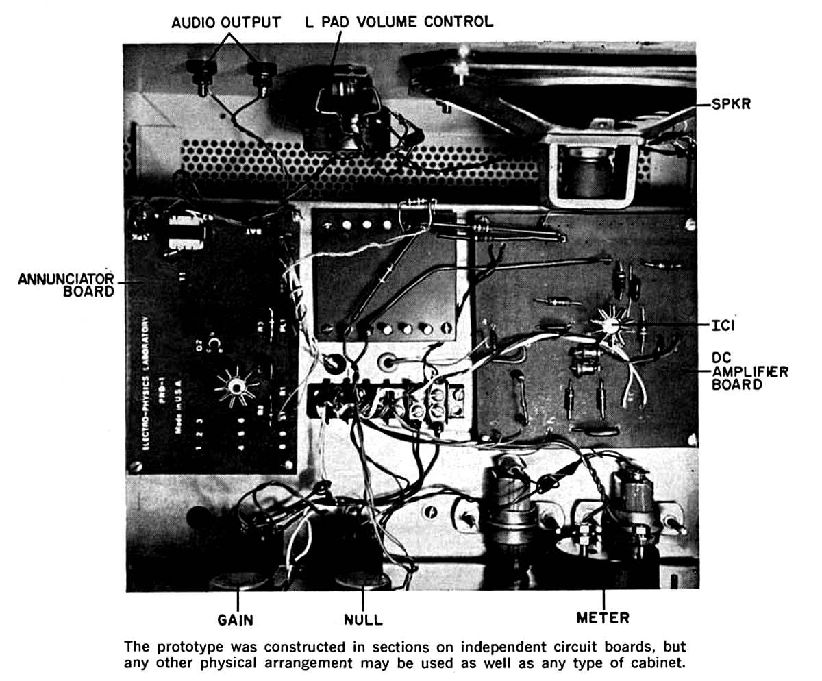
The circuit can be assembled on a perf board or a printed circuit board. Be careful to avoid heat damage when soldering the IC and other semiconductors. Observe the polarity of the electrolytic capacitor. Either a well-filtered dual 9-volt power supply or 9-volt batteries may be used for the power source. Use a suitable metal chassis to house the detector, with the meter and all controls on the front panel.
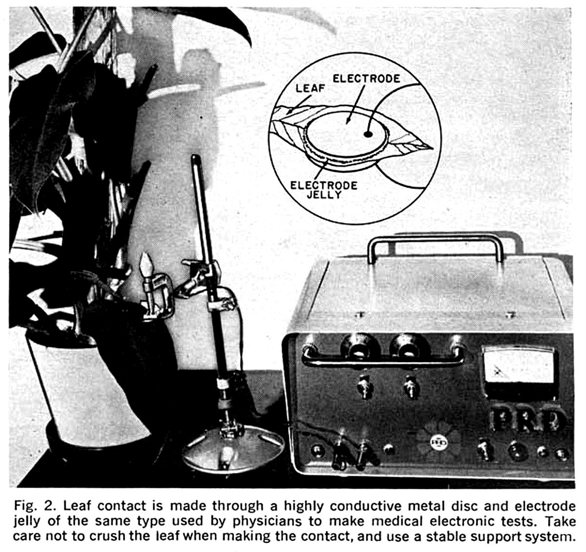
Connections to Plant. The pickup electrodes which are attached to the plant (see Fig. 2) can be of almost any shape and any metal that has good conductivity. Stainless steel or silver electrode pairs will work very well. Use of dissimilar metals can cause undesirable electrolysis. The effective size of the electrodes can be determined experimentally, but normally would be less than one inch in diameter. If it is found that the leaf resistance is very high, a larger diameter on the electrodes is required. If the plant has thin, moist, semi-opaque leaves, a smaller electrode is used. Leaf conductance can be enhanced by using electrocardiographic electrode contact cream, such as ECG KONTAX (Cat. No. 391, Birtcher Corp., Los Angeles, CA 90032). It is water soluble and should be wiped off plant leaves after the experiment is complete. Give the leaf a good rinse after that. Connections to the electrodes are made through a shielded pair cable. The electrodes are insulated from the metal clamp by pieces of plastic with the leaf gently compressed between the electrodes. Using the bridge resistor values shown in Fig. 1, the resistance between the electrodes should not exceed 250,000 ohms. Also keep in mind that the plant generates a small current of its own which, depending on the setting of switch S2, is superimposed on the excitation current flowing in the circuit.
THE BACKSTER EFFECT
Cleve Backster, one of this country's leading authorities on the polygraph (lie detector) connected a pair of electrodes to a leaf of a dracaena massangeana while it was being watered. Surprisingly, the plant's psychogalvanic reaction pattern resembled that of a human subject exposed to emotional stimulation.
In further tests, Backster decided to ignite a match and burn the leaf to which the electrodes were attached. At the instant that the thought image occurred in his mind, a dramatic change appeared on the plant's polygraphic readout. Tests were carried out on other living matter including paramecium, fresh fruits and vegetables, amoeba, mold cultures, scrapings from the roof of a human mouth, and yeast. All showed similar results. It would appear that there is an unknown communication between all living things, outside the orthodox electromagnetic spectrum. For exampling, placing plants in lead-lined, Faraday-screened cages, fails to suppress the phenomenon.
It also appears that plants form some sort of emotional attachment to their owners. Cleve Backster has reported that one plant responded to his emotional attitude at a distance of 1000 miles. Obviously, much work remains to be done in this area.
Theory of Circuit Design. The resistance of the plant leaf, when connected to BP1 and BP2, forms part of a Wheatstone bridge with the other arms formed by R1 and the two portions of R2. Power for the bridge is supplied by B1 controlled by R3. The final values of R1 and R2 are determined by the type of plant leaf being used. The resistances must be increased when the leaf is thin and sensitive to avoid over-excitation and undesirable side effects.
The input / output polarizer switch S2 permits reversal of the current applied to the plant leaf since living matters tends to saturate and gradually cease to function as an organic resistor.
The offset signal fro the bridge is amplified in IC1, which is guarded by diodes D1 and D2. When S3 is closed, these diodes limit the input voltage to the op amp and protect it from large signals. However, once the circuit is operational and maximum sensitivity is required after M1 has been nulled, S3 can be opened. The output of the DE amplifier is indicated on a meter and can be used to drive a DE pen recorder if a permanent record is desired. The output also drives an audio oscillator (Q1 and Q2) whose frequency is a function of the DE signal. Transformer T1 couples the audio tone to an optional audio tape recorder and to an internal speaker. Capacitor C3 and resistor R16 provide feedback for the oscillator.
The circuit is sensitive to a few microamperes of input current, and when this current changes as a result of plant stimulation, the bias on Q1 changes to alter the pitch of the oscillator. Indicator lamp I1, momentarily activated by pushbutton switch S7, permits intermittent tests of battery voltage and provides for injection of ene markers on a tape recorder since pitch increases when S7 is activated. Power to the audio oscillator is controlled by switch S5.
Transformer T1 provides an audio output for the tape recorder at all times regardless of the position of S6. In one position of S6, R17 serves as a load; while in the other position, R21, an 8-ohm pad, is the load. Volume control is essential since the beep in the audio tone produced by S7 is annoying to listen to and can produce undesired stimulus to the plant.
While performing a particular experiment, the audio signal can be fed to one channel of a conventional stereo recorder, while the other channel is supplied with time markers (from WWV or CHU) or vocal announcements. This permits recording of vocal stimulus to the plant as well as the plant's response.
DC BOOSTER
In tests performed on a tree by the U.S. Department of Agriculture at the University of California in 1964, the application of about 58 volts DC (negative electrode high in the tree, positive attached to stainless steel nail drive in the base of the trunk) showed that leaf density on the electrified branches increased substantially after 28 days. Over a much longer period of time, the leaf growth was 300% over that on the non-electrified branches.
It was also noticed that when a sensitive DC voltmeter was connected between two conductors drive into a living branch (one at the center of a cut-off portion; the other in the layer just under the bark), cutting twigs or branches in any other part of the tree produced a sudden fluctuation on the meter. Even burning a leaf produced a noticeable effect. Not only did the natural voltage rise and fall, at times it even reversed polarity. There is no explanation for this effect.
Conducting Tests. In connecting the electrodes to the leaf, apply just enough pressure to make a good contact with the leaf without crushing it. Place the guard switch (S3) in the closed position to protect the IC from an excessive input signal.
When S1 is turned on, power is applied to the bridge circuit at a level determined by R3. Then turn on S4 to activate the op amp IC. Potentiometer R2 is adjusted for a meter null indication. This null may have to be re-adjusted when the plant is in a non-stimulated condition. Note the pitch of the audio tone coming from the speaker when the plant is quiescent. A change in pitch, as well as in the meter indication, may result when the plant's well being is threatened.
The amount of excitation (via R3), and the state of the input / output polarizer switch S2 must be determined by actual use. Obviously, the gain control (R8) can be adjusted to obtain more or less sensitivity, and S3 can be opened to increase the gain of the DE amplifier.
There is very little more to be said about the use of the response detector. Patience and repetition are the key words. Obviously, also, controlled conditions are a must. The area in which the plant lives must be quiet so that stimuli can be applied. There should be a minimum of power-line noise to avoid fluctuations in the audio and meter indications. There should be no r-f transmitters in the vicinity to cause fault indications.
References
- Electrophysiological Methods in Biological Research, J. Bures, Academic Press, New York, 1967.
- Plant Response as a Means of Physiological Investigations, J.C. Bose, Longsmans, Green & Co., London, 1924. [Available through BSRF in our standard xerographic format: <#B0341, "Plant Response">; or as a PDF: <https://archive.org/details/plantresponseasm00bose>]
- The Nervous Mechanism of Plants, J.C. Bose, Longsmans, Green & Co., London, 1926. [Available through BSRF in our standard xerographic format: <#B0407, "The Nervous Mechanism of Plants">; or as a PDF: <http://oudl.osmania.ac.in/handle/OUDL/21396>]
- Die Elektrophysiologie der Pflanzen, K. Stern, Springer, Heidelberg, 1924.
- "Build a Psycho-Analyzer", R.E. Devine, Popular Electronics, February 1969.
- Plant Physiology, Second Edition, E.C. Miller, McGraw-Hill, New York, 1938.
- "Electric Correlation between Living Cells in Cortex and Wood in the Douglass Fir," E. J. Lund, Plant Physiology, 6:631-652, 1931.<http://plantphysiol.org/content/6/4/631.full.pdf
- "Proof of the Principle of Cell E.M.F.'s," H.F. Rosene, Plant Physiology, 10:209-224, 1935. <http://plantphysiol.org/content/10/2/209.full.pdf>.
- "Evidence of a Primary Perception in Plant Life," C. Backster, International Journal of Parapsychology, 10:4, Winter 1968. <http://rebprotocol.net/clevebaxter/Evidence of a Primary Perception In Plant Life 23pp.pdf>
- "Electronics and the Living Plant," L.G. Lawrence, Electronics World, October 1969. <Full-text>
- "Experimental Electro-Culture," L.G. Lawrence, Electronics World, February 1971. <Full-text>
- "Magnetotropism: A New Plant Growth Response," L.J. Audus, Nature, Jan. 16, 1960.
- "Plants Are Only Human," W. McGraw, Argosy, June 1969.
- "Electricity in Plants," B.I.H. Scott, Scientific American, October 1962. <http://www.scientificamerican.com/article/electricity-in-plants/>
Originally published in "Popular Electronics" (June 1971). Browse AmericanRadioHistory.com for complete issues of P.E. and many other historical radio and electrical publications in PDF format.
Return to the BIO-ICOMM Project homepage or the Bibliography of L. George Lawrence.