

This is an experimental arrangement developed by the author to test certain theories relative to stimulating plant growth in a very high voltage electro-static field. Details on the equipment built for the experiment are detailed and some of the background on the "why" of electro-culture is discussed.
HANGING your pet geranium upside down in the cellar all winter isn't necessarily all it takes to grow a beautiful plant next spring. Of course, amateur horticulturists — as well as professionals — have any number of theories about how you can automatically have a green thumb; but several historical and many more recent experiments have shown that successful gardening isn't just a matter of fertilizing, watering, and tender loving care.
Indeed, only a handful of people realize the role that natural electricity plays in the development of plant life. Yet, in 1902, physics professor S. Lemstroem, after a trip to the northern polar regions, decided that the rapid growth of vegetation during the short arctic summer was due to the unique electrical conditions of the atmosphere in those latitudes. Back in his laboratory, Professor Lemstroem reproduced the assumed arctic conditions by increasing the atmospheric current (which normally flows from the air to the plant) by placing a wire with a high static charge on it (generated by a Wimshurst machine) over a plant. An increase in plant yield was noticed.
Study of electro-culture (as the science is called) began with basic experiments by a Dr. Mambray in England in 1746. Later, in 1879, a French scientist, L. Grandeau, saw dramatic possibilities in the field which he described in a paper "Influence de l'Electricite Atmospherique sur la Nutritio des Vegeaux." But the real break came in 1902 with the Lemstroem experiments.
MORE INFORMATION?
- "Electronics and the Living Plant", L.G. Lawrence, Electronics World, October 1969.
- Plant Physiology, E.C. Miller, McGraw-Hill Book Co., New York, 1938. <>
In more recent times, other experimenters extended the work to treatment of viable seeds using radio-frequency and ultrasonic methods. The r-f techniques involved frequencies above 30 MHz applied for a few seconds to seed bag placed into r-f tank circuits. Ultrasonic schemes involved the brief dipping of bags into bath agitated at frequencies up to 1 MHz. Plants grown from seeds treated in this way had yield profiles ranging from fair to excellent.
Fertilizers Spoil Picture. It was the invention and use of cheap chemical fertilizers that effectively suppressed electro-cultural engineering. Today, however, we are in the position where nitrate pollution by these very fertilizers threatens not only our water supply but the entire ecological panorama as well. Thus it would appear that the revival of electro-culture is not only desirable but imminently necessary.
Experimenting with electro-culture is largely the same as building a stereo amplifier or a digital voltmeter. For one thing, high static voltages are involved and a good degree of professionalism is required to obtain good results. (Keep in mind that we are concerned with living plants, which have their own peculiarities and may not always respond as expected - only large-scale trends are important.)
Typical electro-culture systems frequently operate unattended for long periods of time in an open-air environment. This requires heavy-duty construction in both the electrical and mechanical aspects of the equipment.
However, expenditures can be kept low by using surplus-type materials. In the case of an experimental electro-culture system using high-voltage discharge, the cost of a typical exciter unit can be below $35.00.
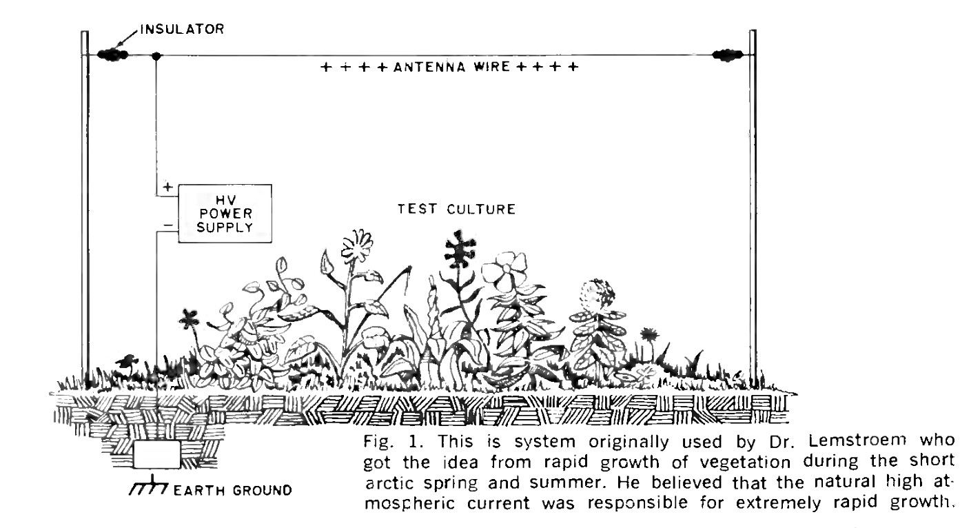
Basic System. A schematic of a Lemstroem type of electro-culture system is shown in Fig. 1. Here, the positive terminal of the high-voltage power supply is connected to the overhead wire, with current return through a ground path. Potentials are as high as 20,000 volts — up to 60,000 volts for short periods of time. While natural atmospheric currents range between 10-16 and 10-15 amperes, the excitation provided by the high-voltage wire provides currents around 10-12 or 10-11 A, as measured by a sensitive electrometer. In open-air experimental fields, the height of the overhead discharge wires with respect to ground may be front 3 to 10 feet. The height above ground naturally affects the amount of atmospheric current. Remember that the high voltage essentially serves as a "current carrier" — appropriate current values cannot be generated under other than high-tension conditions.
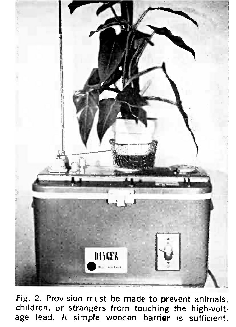
High-voltage electro-culture systems may take the form shown in Fig. 2. The apparatus was designed to investigate the susceptibility of many different plants to stimulation. The equipment generates ozone (O2) and must be used in well-ventilated areas only.
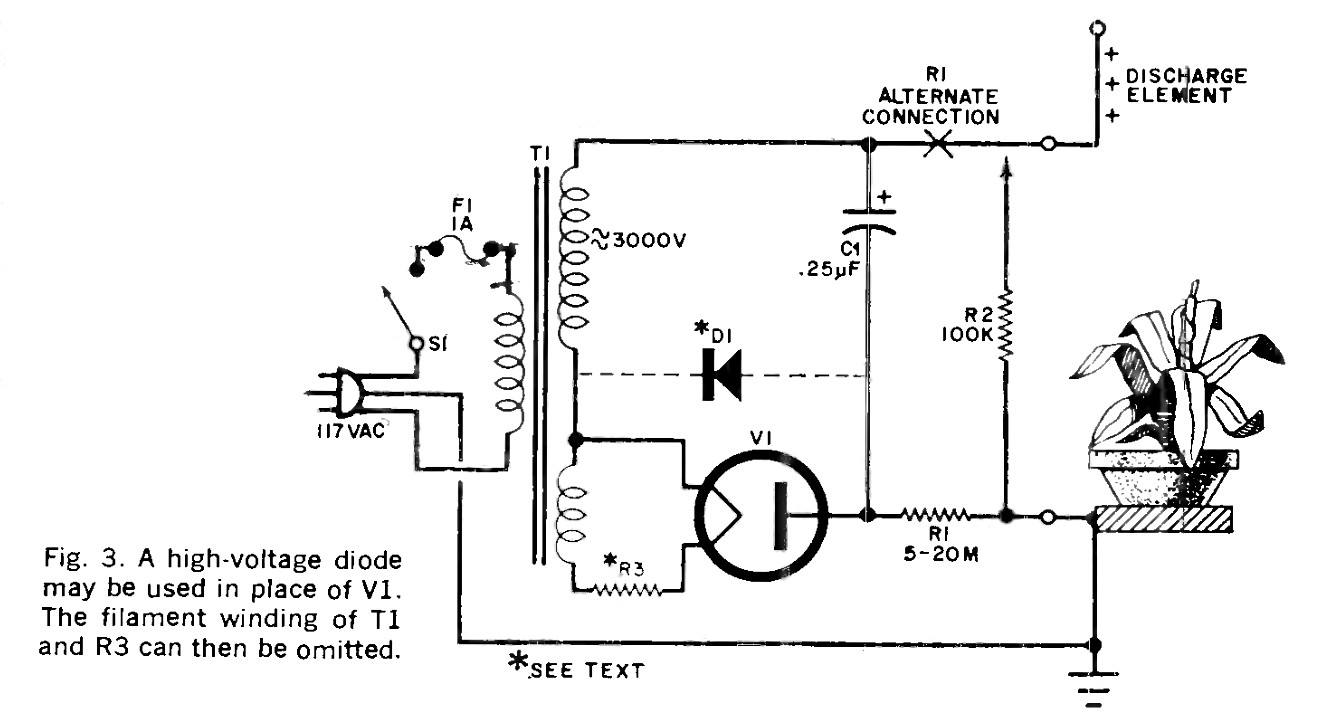
An electrical schematic of this system is shown in Fig. 3. Transformer T1 has an output of 3000 volts rms. After rectification, the effective dc is approximately 4200 volts. A dropping resistor may be necessary on the filament winding to obtain the correct voltage for the rectifier. If leakage current in the reverse mode can be tolerated, a high-voltage rectifier diode may be used instead of the tube and filament winding.
The 3000 volts dc generated is highly dangerous to touch.
Resistor R1 (made up of several resistors in series) serves as a current limiter and can be anywhere from 5 to 20 megohms, the latter value limiting the current to 210 µA in the event of an accidental short circuit. Resistor R1 may be in series with either the positive or negative output terminal.
Resistor R2 is connected to two pieces of high-voltage cable with the connections and resistor thoroughly wrapped with high-voltage insulation so that the resistor is actually imbedded in the cable. Put insulated alligator clips on each end of the cable. This resistor forms a safety discharge shunt and must be connected across the output terminals when the apparatus is shut off to discharge capacitor C1 and the antenna structure ("discharge element" in Fig. 3).
- C1 — 0.25-μF, 7500-volt capacitor
- F1 — 1-ampere fuse with holder
- R1 — 5-to-20-megohm resistor (see text, ½ watt each)
- R2 — 100,000-ohm, 2-watt resistor
- R3 — See text
- S1 — Spst slide or toggle switch
- T1 — Oscilloscope transformer; secondaries: 3000 volts and 6.3 volts
- V1 — Half-wave, high-voltage rectifier tube
- Note — Alternate rectifier diode D1 (IR 67 D-050H55FNN) can be used as shown by dotted line. See text.
- Misc. — Large plastic container, 3-lead power line, mounting plate, insulators, high-voltage cable (10-kV test), hookup wire, hardware, ground plate for pot.
PARTS LIST
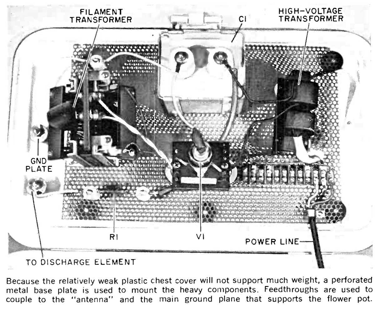
The power supply's physical layout is shown in Fig. 4. For safety's sake and good appearance, the entire power unit is mounted on the lid of a plastic camping chest. Ceramic insulators are fastened to the lid to provide connections for the discharge element and ground wires. A simple ground electrode is inserted into the moist dirt (earth mixed with moss is good) in the pot and the pot sirs in a metallic basket which is connected to the negative terminal of the supply. The antenna or discharge element is connected to the positive terminal and consists of a simple metal rod.
The 117-volt line cord is a grounded 3-wire type, with the green (ground) wire connected to the perforated-steel mounting plate on which the plant basket sits. The high-voltage transformer is mounted on insulators and the rectifier tube socket is mounted on insulators on a Bakelite terminal board. The string of resistors comprising R1 is fastened to stand-off insulators of the ceramic type. In the model shown in Fig. 4, a separate transformer was used for the tube filament supply with dropping resistor R3 mounted on the Bakelite terminal board. The entire high-voltage section is wired with high-voltage cable tested to 10,000 volts dc.
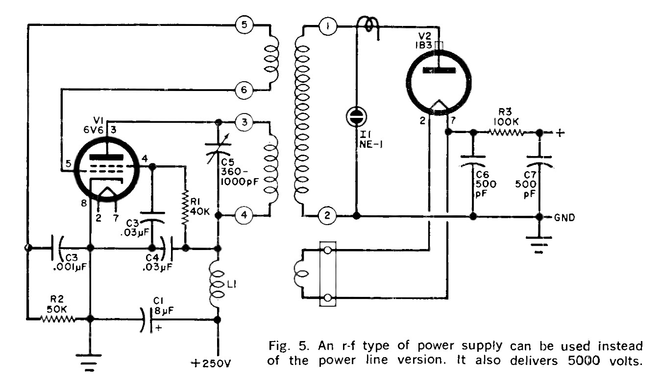
R-F High-Voltage Supply. A schematic for a radio-frequency high-voltage unit is shown in Fig. 5. It is an inexpensive and slightly less dangerous alternate to the supply described above.
Effective dc output of this supply is 5000 volts at 200 microamperes maximum. Thus, should the supply's output electrodes be touched accidentally, an unpleasant, but non-lethal, shock will be experienced.
Electronically, the supply is comprised of a straightforward feedback oscillator. Optimum oscillator frequency is approximately 225 kHz. Tube V2 is a half-wave rectifier. The supply may be constructed on a simple chassis and installed in a manner similar to the one shown in Fig. 2.
Note, however, that the transformer specified for T1 does not have a filament winding for the rectifier. A filament loop may be added simply by placing one turn of No. 20 insulated high-voltage wire around T1's ceramic base, being careful to maintain spacing from the tuned r-f circuit. (Follow the instructions packaged with the transformer.) A VTVM or similar high-impedance meter my be used to measure output voltages without excessive loading. After wiring is complete, remove rectifier tube V2 and adjust the oscillator for maximum output power by tuning capacitor C5 with an insulated alignment tool. Place a "gimmick" or single-turn coupling loop with a neon lamp on the output of T1 as shown in Fig. 5 and tune the circuit until the lamp attains maximum brilliance. Remove the neon lamp and gimmick after tuning is complete. In operation, it is proper for the filament of the 1B3-GT to glow a dull red.
- C1 — 8-μF, 350-volt electrolytic capacitor
- C2, C4 — 0.03-μF, 600-volt capacitor
- C3 — 0.001-μF, 600-volt capacitor
- C5 — 360-1000-pF tuning capacitor (J.W. Miller 160-A or similar)
- C6, C7 — 500-pF, 10-kV capacitors (TV type)
- I1 — NE-1 neon lamp
- L1 — 2.5-mH r-f choke (J.W. Miller 4537 or similar)
- R1 — 40,000-ohm, 1-watt resistor
- R2 — 50,000-ohm, 1-watt resistor
- R3 — 100,000-ohm, 1-watt resistor
- T1 — High-voltage, r-f transformer (J.W. Miller 4525 or similar)
- V1 — 6V6 tube
- V2 — 1B3 tube
- Misc. — Suitable high-voltage and filament supply, insulated chassis, tube sockets, high-voltage wire for 1B3 filament winding (see text), cap for 1B3
PARTS LIST
Safety Precautions. Due to the inherent shook hazards involved in either of the systems described here, they should be operated behind a simple wooden barrier marked to keep away "unauthorized personnel." The experiment may then be operated near a window or other well-lit area indoors. The equipment may also be operated outdoors, preferably in a fenced-in private garden, provided it is protected from rain and moisture and the proper precautionary measures are employed. With component values shown, an "antenna" height of three feet is suggested — depending on local wind conditions and ambient aerobic moisture content.
When it is necessary to work on a plant or water it, turn off the power and connect safety shunt R2 across the high-voltage terminals. When watering, avoid wetting the electronic equipment and the high-voltage discharge element. When you are through working on the plant, remove the safety shunt, get out of the way, and turn the power back on.
Always keep safety uppermost. in your mind. Physically protect the electro-culture experiment from strangers, children and animals.
What Can You Expect? According to data advanced by Dr. K. Stern and others, a true increase in yield of 45 percent for a well-cultivated field can be expected. Yield differences are determined by comparing results against non-treated control cultures of the same type. Some plants give very low yield unless well-watered. Peas ant carrots are in this group. Further, electric treatment must be stopped if days are hot and sunny. A simple photoelectric relay circuit, connected in series with the power line, provides adequate control for this purpose.
Note that plants are mavericks in many ways and do not necessarily show uniform yield patterns. Electronically peaking, being living organisms, species utilize the energy contained in the phosphate bonds of adenosine tripitosphate (ATP) to drive reactions which lead to maintenance and growth of cells, tissues, etc. This ATP is produced from adenosine diphosphate (ADP) by processes involved in aerobic respiration, fermentation, and electromagnetic bionuclear constituents of photosynthesis. In many ways, plants are organic semiconductors and apparently feature electron transport systems which, in higher plant mitochondria, are exactly the same as those for animal mitochondria in ways of generating enzyme.
However, taken together, science has only a vague idea why plants react applied electro-culture and related methods mentioned earlier. The field is wide open for experimentation and improvement, and it certainly has exceptional hopes for the future.
Originally published in "Popular Electronics" (Feb 1971). Browse AmericanRadioHistory.com for complete issues of P.E. and many other historical radio and electrical publications in PDF format.
Return to the BIO-ICOMM Project homepage or the Bibliography of L. George Lawrence.