Voltage Changes in Hand-Held Dipoles (“Dowsing Rods”) Resulting From Variable Electromagnetic Radiation
By John S. Janks
Abstract
“Dowsing Rods” have been the subject of speculation for centuries. However, serious scientific measurements have only been made in the past few decades. Recent research has made a serious effort into quantifying their behavior. One of the fruits of new research has been that “dowsing rods” share many of the same physical properties as dipole antennas. Some of these characteristics include size and shape (the “rabbit ears” that sat on TVs for decades were dipoles), response to electromagnetic energy, increased metal content increases rod activity, and that connecting the rods with conductive metal wire stops all activity.
The research presented here delves deeper into the relationship among hand-held dipoles (“dowsing rods”), changing electromagnetic energy, and the characteristics of the direct current generated by electromagnetic radiation as it occurs in the human body.
If there is no potential, hand-held dipoles make no movement and current measurements on the human body are at background levels. However, once a potential-generating source is included (e.g., a buried metallic can) the dipole rods move, currents measured in the body change, probably due to the creation of a parasitic capacitor.
A study site chosen near the west-to-east landing strip of a major airport provided changing electromagnetic radiation by the aircraft. The experimenter remained stationary and recorded a series of voltage changes as he faced west, south and east with all the aircraft landing west-to-east. As currents in a dipole antenna are dependent upon wavelength and antenna size, the connection to the voltmeter was shifted from the tip of the dipole, to its middle, and at the point where it bends.
The following points summarize the research findings:
- Electromagnetic energy generates a direct current in two hand-held dipoles,
- Dipoles will move if the source of the electromagnetic energy changes while the experimenter remains stationary,
- Current levels are variable if the position of the voltmeter is moved along the length of the dipole.
Purpose of This Paper
This paper voltmeter data acquired through hand-held dipoles (“dowsing rods”) on a Sperry DM-350A Voltmeter. The user was stationed nearby a landing aircraft; the aircraft supplied electromagnetic energy from their transponders. That there was a direct relationship between passing aircraft and dipole movement has been established for years. [1] However, without quantitative data, the same “Ideomotor Effect” was again used to explain rod movement.
Dipoles
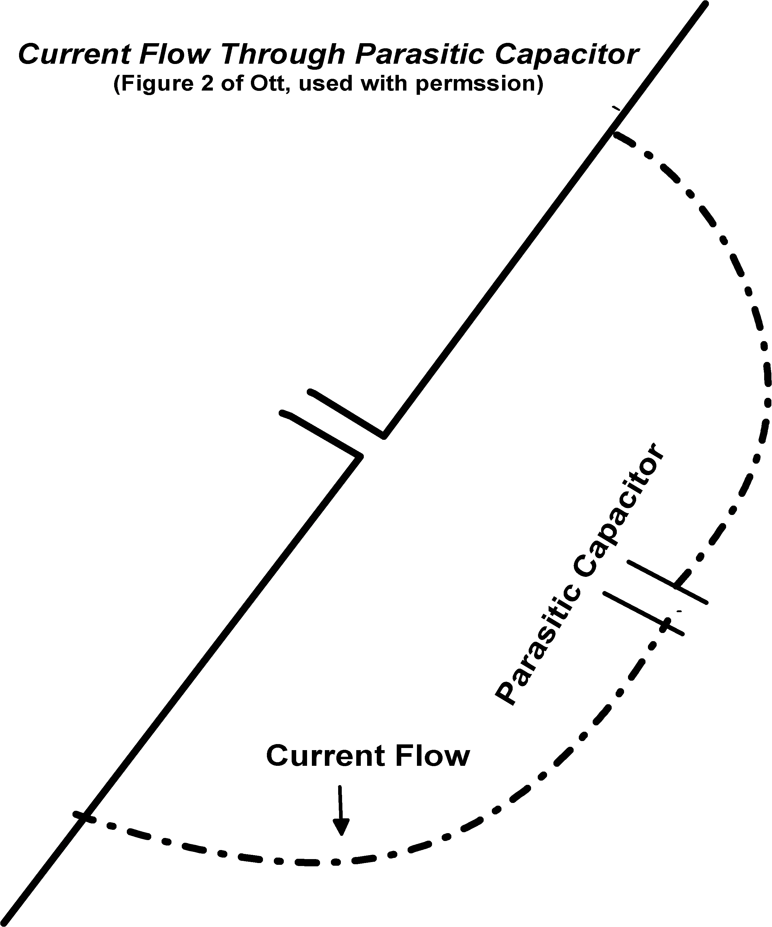
The data published today originated from the ideas of one of the world experts on dipoles today, Dr. Henry Ott. He made his finding understandable to the average non-PhD electromagnetic physicist, beginning his introduction to dipoles in a series of three papers entitled, “Dipoles for Dummies (Parts I-III)”. [2] Importantly to our work, he demonstrated that the dipole rod does not necessarily have to have a uniform distribution along it. Whether the charge is distributed uniformly depends both upon the length of the rod and the wavelength of the electromagnetic field. The comparison of hand-held dipoles to the old “rabbit ears” seen on so many TVs decades ago can be seen in Figure 1. Ott's circuit made use of a “parasitic capacitor” through which current flowed. It is a straightforward extension of Ott’s dipoles to the hand-held dowsing rods.
The comparison between dipoles and dowsing rods needed significant testing before even the basic claims could be made. Those wishing to review the experiments and judge for themselves can read several papers on the subject, although the original (and still) goal of our work is to find cost-effective answers to IEDs, tripwires and landmines. [3][4]
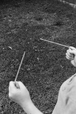
Figure 1. Left image is a diagram of current flow through the two L-shaped rods of a dipole antenna. Image at right is a photograph of a user locating a buried object using L-shaped rods.
Experimental Design
Caveats
This set of experiments used simple tools to gather data and make observations. First, we used landing aircraft transponders as the source of electromagnetic energy. Some variations may occur because of numerous frequencies, landing speeds, etc. that affect the voltage recorded.
Second, we believe that we are measuring the voltage created by the parasitic capacitor generated in our bodies because of the electromagnetic radiation, not the radiation itself.
Third, the current measured during the aircraft landing procedure did not produce a continuous line or even a common distribution. This is likely in part because the voltmeter was attached to different sections of the dipole rod (Figures 2, 3, 4).

Figure 2. Voltmeter attached to dipole rod with copper wire. The positions were moved to observe changes in voltage.
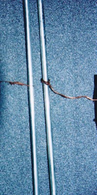
Figure 3. Details of copper wire from voltmeter attached to middle “M” position on rod.
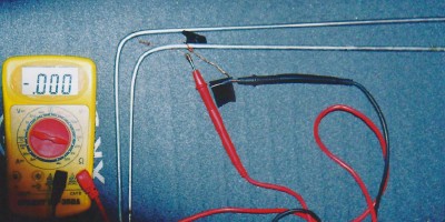
Figure 4. Photo showing voltmeter attached via copper wire near the bend in the dipole rod.
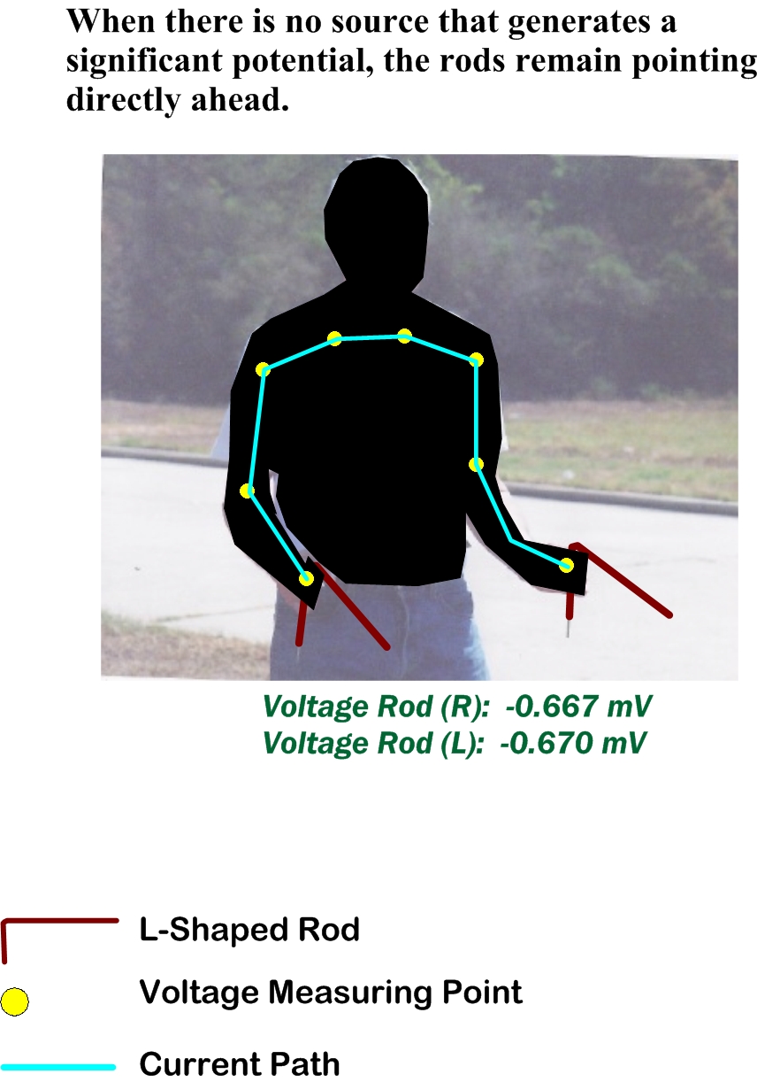
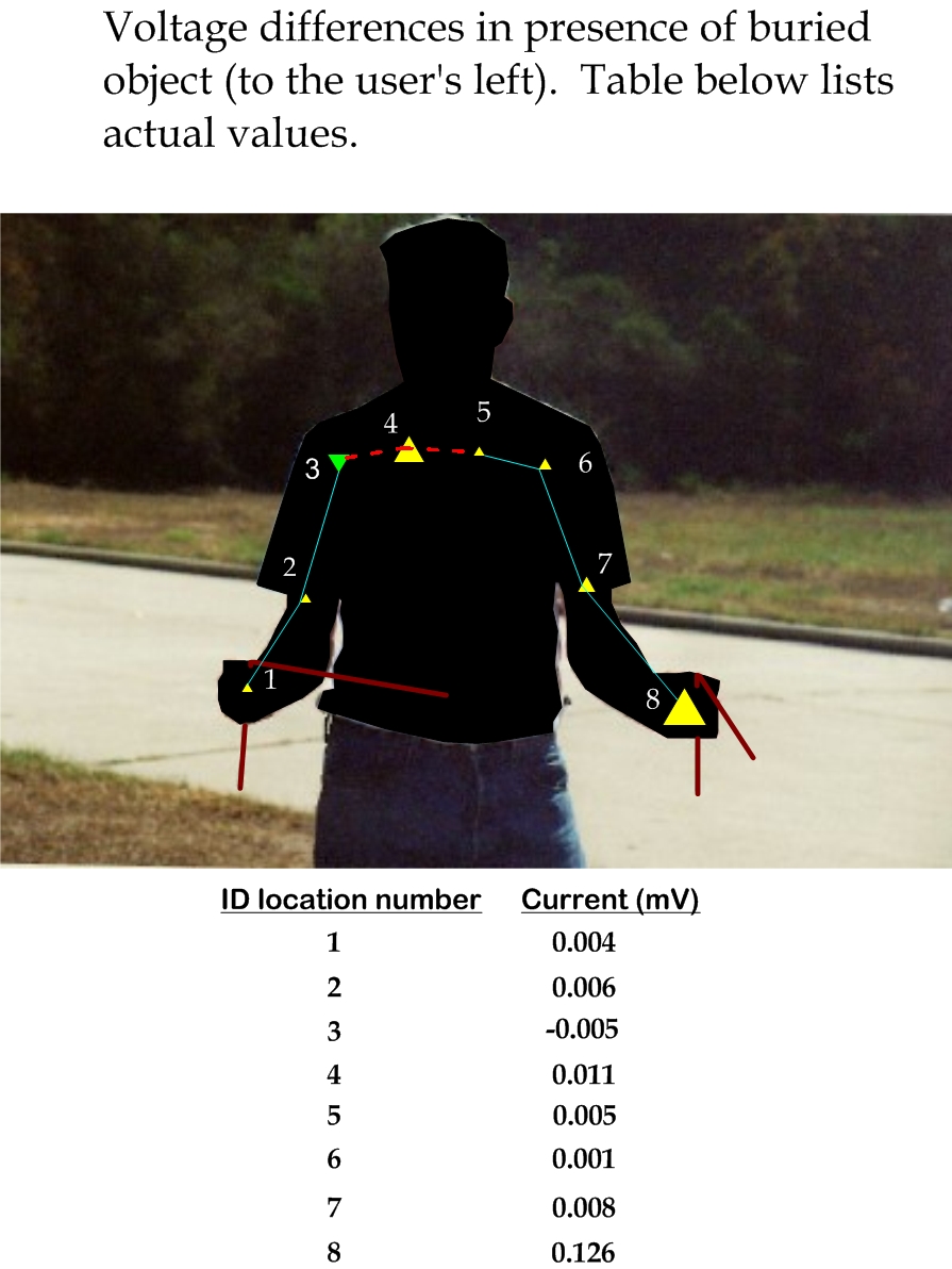
This set of tools was first tested on a buried can to determine if there is any change in voltage with and without the presence of a nearby buried quart metal can (Figure 5). Where no object was buried, the measurements were at background levels. In the right image, a quart metal can was buried a few meters away. One point (#3) was negative, and next to it, #4, the second highest reading. We estimate that this is probably the area of the parasitic capacitor. The dipole rod in the user’s right hand is pointing towards the buried can. It’s voltage was 0.004 mV. The rod in the user’s left hand, however, had the highest value, 0.126 mV and about two orders of magnitude greater than the right hand’s value. This experiment demonstrated basic tools can be sensitive enough to create rod movement.
Figure 5. Left, voltage was tested at yellow points and too low to measure accurately. Right image shows the changes when a quart metal can is buried a few meters to the user’s left. Triangles estimate relative currents. Highest value was at point 8 (0.126 mV). Note only one value in the set (3) changed sign.
Experimental Location: The site is on the public right-of-way on the north side of Turkey Creek, Houston, TX (Figure 6).
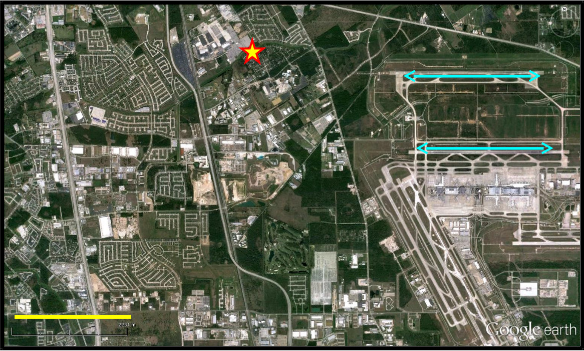
Figure 6. Large view showing E-W landing strips (cyan lines). Yellow and red star show the study area location. Solid yellow line at lower left represents 2225 meter.

Figure 7. Directions experimenter faced during data collection. Pink bar at lower left is 130m.
Experimental Design:
The experiment was designed so that the experimenter would remain stationary and face west, south and east as aircraft landed a few hundred meters away always from west to east. One goal was to see if a direct current was generated by passing aircraft in a voltmeter attached to two hand-held dipoles (Figure 7).
The aircraft are on landing approach just a few hundreds meters to the south (Figure 8). Thus, the experimenter can see how rod movement behaves as he changes the direction he is sitting. The only time the voltmeter ever measured any current above background was when an aircraft was landing. We are assuming from this that the source of the electromagnetic radiation is likely the plane’s transponder.
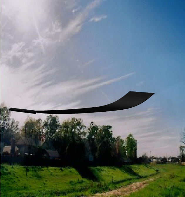
Figure 8. Generalized W-E landing pattern as seen from the experimental site.
Rod movements occurred as they had previously (e.g., the outer rod moves more than the inner one), but voltage changes varied considerably.
The letters seen in the following figures correspond as follows:
- T = tip of the rod
- M = middle of the rod
- B = bend in the rod
- E,W,S = direction the experimenter is facing
Results
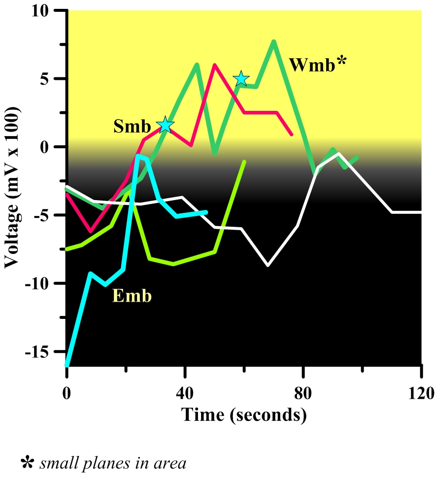
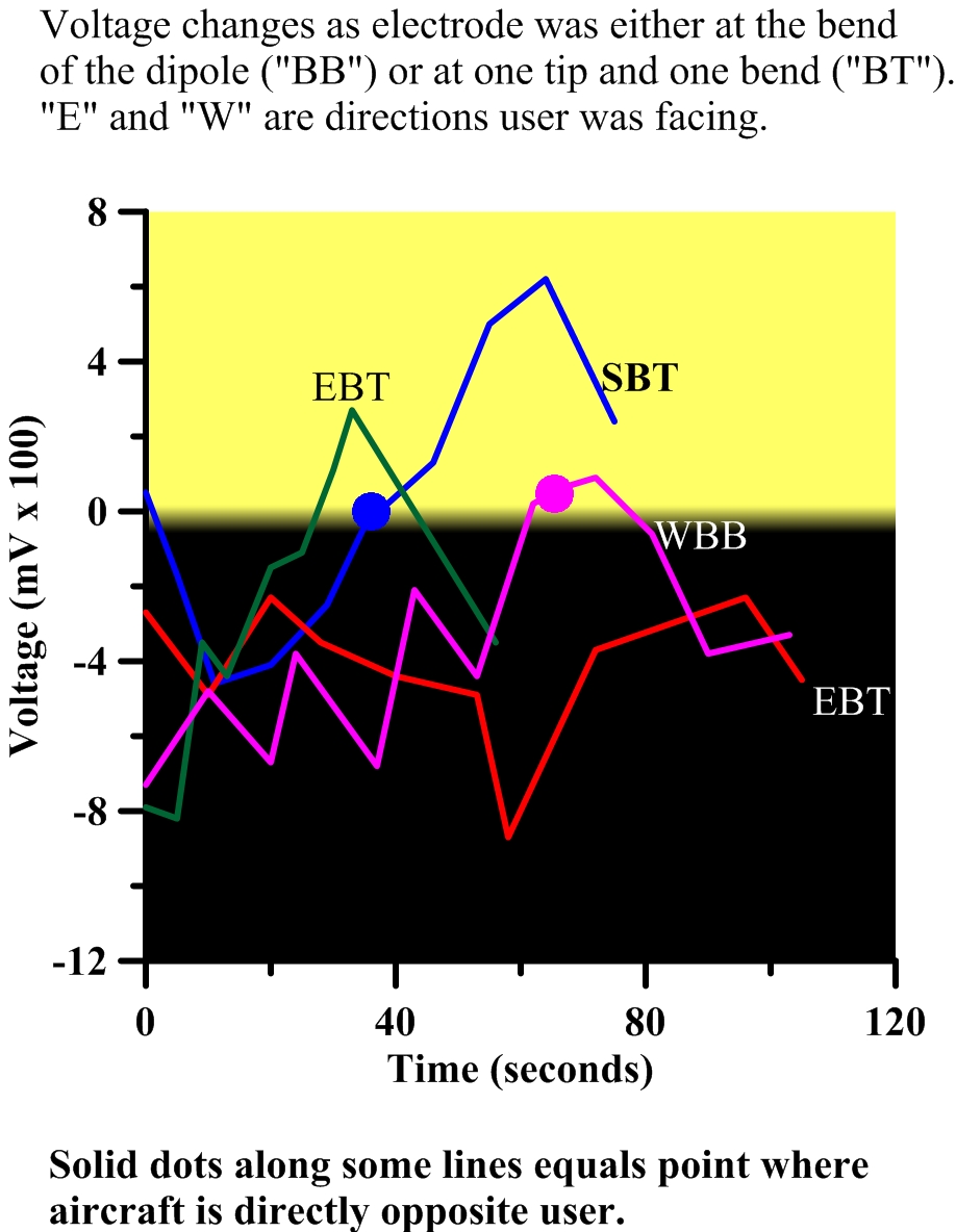
Figures 9, 10, and 11 show the current voltage patterns as the experimenter faced west, south and east, respectively. The black background on each graph represents negative values. Each plot line was assigned how the voltmeter wires were attached to the longer arm of the dipole. Thus, “tt” means readings were taken from the tip of the dipole, “bt” means one rod was connected at the bend and the other at the tip of the dipole. As the user faced west, the voltmeter connected to the middle of the rods recorded the most positive values. Most measurements that included the bend “b” were usually the most negative. When the experimenter faced south, the voltages all appeared to move from negative to positive voltages.
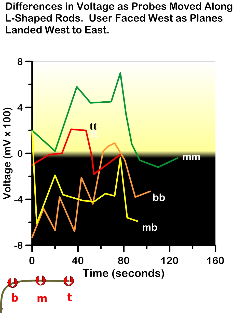
Figure 9. Facing west. The highest value was when the mid sections were connected (“mm”).
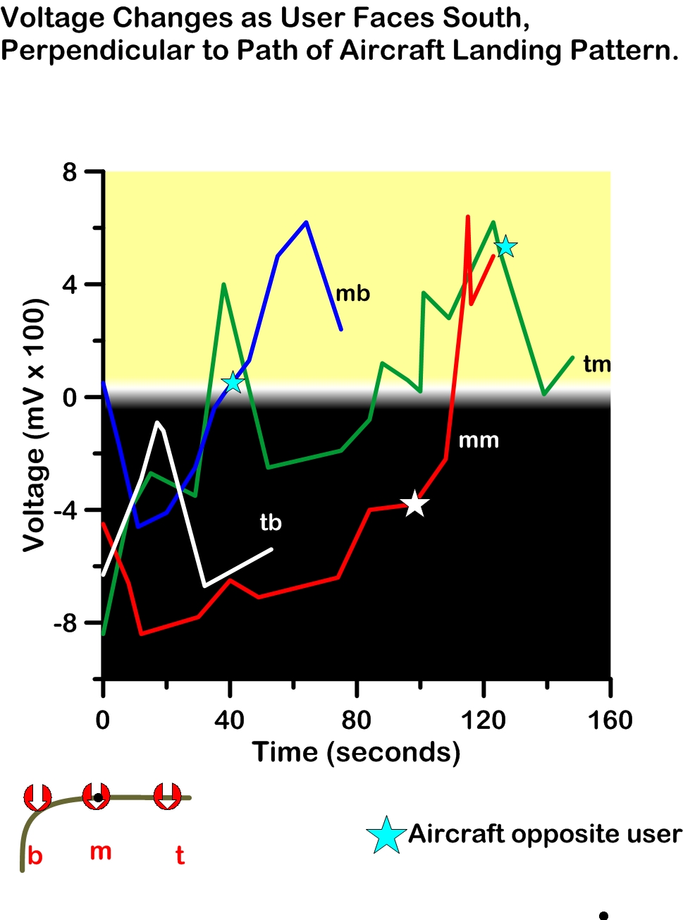
Figure 10. Although the same ranges, when facing south, more of the data points were in the negative area.
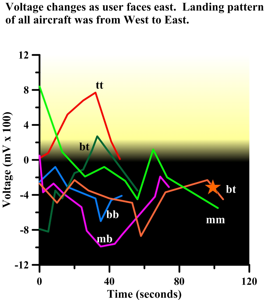
Figure 11. User facing due east. Most of the reading (other than “tt”) are negative.
Figure 12 is a collection of “mb” values (left side) and “bt” and “bb” (right) regardless of the position of the experimenter. There is little consistent correlation of the data curves, although generally, values taken when the experimenter faced south and west were usually higher than when he faced east.
Figure 12. Left image illustrates how currents change with “m” and “b” combination. Most trend upwards. The Right image compares “b” with “t” positions in all three directions. The stars on left and circles on right are points where aircraft was directly opposite experimenter.
Discussion
One of our goals, to see if a direct current was generated, as an experimenter remained stationary and a source of electromagnetic energy changed position was confirmed. The first step was to determine if a human being holding metal rods could act as parasitic capacitors (Figure 5). With nothing to create a potential, the rods pointed straightforward and the measuring points read no higher than background. However, when a potential was created by burying a quart can a few meters to the user’s left, not only did the rod farthest away move, but there were notable changes in the charge at each point, and one even had a sign change. Presumably, this is where the parasitic capacitor was located.
As stated earlier, it has already been established that dipoles moved when aircraft passed nearby, but no precise mechanism had been documented.1 Until recently, few data gathering reports have been published to provide answers to the question of why dowsing rods (“dipole antenna”) moved. The purpose of our research has always been to have this methodology tested in locating buried objects such as landmines, IEDs, and tripwires.
Establishing the relationship between dowsing rod/dipole antenna should add to the seriousness of the physical evidence. Below are a few of the physical observations, taken over the past few years that have gone unexplained:
- Dipoles/dowsing rods point towards each other when they are either above (tripwires) or below (power lines) linear objects. Naturally-occurring electromagnetic fields are the likely energy source. [5]
- The rod farthest from the target moves the most.
- If dowsing rod/dipoles are connected by a conductive wire, there is no reaction.
- Surface rod movement patterns mimic the shape of the buried object, and are proportional to its size.
- Water cannot be detected. The method can detect objects buried in cluttered, wet soil covered by surface trash.
No measurable source that would make the rods move has ever been identified.
After reviewing the science behind dipole antennas, it became obvious that they bore many similarities to what have been traditionally called, “dowsing rods.” A partial list of these common characteristics is:
- Both are “L-shaped” metal rods that respond to electromagnetic energy (think of the old “rabbit ears” that were on every TV decades ago).
- Neither needs to be grounded.
- A single rod will work because the dipole system will establish its own second rod.
- Adding more metal to the end of the rod makes it more effective.
Ott also noted that currents are not always evenly distributed along the dipole antenna.6 How the current is distributed depends upon the length of the dipole antenna and wavelength of the electromagnetic energy. The experiments here sought to determine if measurable current differences in hand held dipoles occur when the voltmeter is connected to the bend (“b”), middle (“m”) or tip (“t”).
Direct Current Measurements in Hand-held Dipoles
The experimenter remained stationary as described above, and allowed the aircraft to provide a moving source of electromagnetic energy. This study makes it clear that although the data correlations are not smooth, where the voltmeter is attached to the dipole causes large changes (relative) in the polarity and current level. Why these currents distribute themselves in this manner is unknown. In Figure 8, the experimenter is sitting towards the west and opposite the incoming aircraft. Only the measurements from the middle of the rods are almost all positive. Those measurements taken from the rod tips are about equally positive and negative, but the variance from zero is the smallest. Those taken from the bend in the rods (“bb”) or one at a bend and the other at the middle (“mb”) are the most negative, and remain there over the course of the measurement.
When the user faced due east, most measurements except for the rod tips (“tt”) remained negative. The only observation set that had some consistency is when the user faced south and recorded measurements as the aircraft passed from his right to his left. Except for one short run (“tb”) the voltages started in the negative and increased into the positive.
It is noteworthy that while the currents in the voltmeter change as described as seen in Figures 9 through 11, the movement of the rods moved as have been documented previously. For example, the rod farthest from the aircraft moved the most.
Isolating individual combinations, such as “mb” and “bt” from all three directions are shown in Figure 12. The left side of Figure 12 indicates that the most positive patterns were found when the experimenter faced west or south. Conversely, the most negative readings came from the user facing to the east. Measurements from the bend in the dipole rod (“bt” or “bb”) displayed no recognizable pattern, although those measurements including the bend in the dipole rod typically had some of the lowest negative values.
Conclusions
This paper shows that hand-held dipoles (“dowsing rods”) respond to a potential created by a change in the electromagnetic field. In the study, commercial aircraft landing west-to-east generated dipole rod movement as the aircraft passed. These electromagnetic field changes created a direct current and a parasitic capacitor in the hand-held rods.
The direct current voltage and polarity depended on whether the user was facing east, south or west. It has been noted that dipole currents are not necessarily uniform along the length of the L-shaped dipole rod, but rather depends on the wavelength of the signal and the length of the rod. Our findings support this conclusion.
Although many still believe that “dowsing rods” are a creation of the subconscious mind, the amount of hard data piling up against the “Ideomotor Effect” is reaching a tipping point. This study adds further evidence that the “mysterious dowsing rods” behaves the way they do when locating underground objects, wires, or above ground trip wires because they are in reality dipoles responding to natural electromagnetic fields.
References
- Janks, J.S., 2010, “Dowsing Rods: Empirical Evidence and Applications for Charting the Subsurface”, J. Borderland Sciences, IE ed.
- Ott, H. W., 2002, “Dipoles for Dummies, Parts 1, 2 & 3,” Henry Ott Consultants, <www.hottconsultants.com>.
- Janks, J. S., 2011, “Low Technology Method to Locate Landmines, IED, and Tripwires,” Scribd, <http://www.scribd.com/doc/65351175/Low-Technology-for-Detecting-Landmines-IEDs-and-Tripwires>, pp. 1-11.
- Janks, J. S., 2011, “How to Stop Landmines from Killing Soldiers Now,” Scribd, <http://www.scribd.com/doc/66873198/How-to-Stop-Landmines-and-IEDs-From-Killing-Soldiers-Now?, pp.1-12.
- Hendry, J., 2009, “Surface Waves: What Are They? Why Are They Interesting?,” 4th SEAS DTC Technical Conf., Edinburgh, 10 p.
- Ott, H. W., 2000, “Understanding and Finding The Invisible Antennas in Your Design,” <www.hottconsultants.com>, 18 p.

