
Theory and Physics of Abrams Electronic Reaction
by Thomas Colson — from "Introduction to Electronic Therapy" (1936)
The electronic reactions are based upon the electronic theory of matter wherein the atoms of all matter include protons and electrons in their makeup and the arrangement and number of these protons and electrons account for the differences in all substances. We need not go into the specific relations of the protons and the electrons here, but to any one desiring to do so is referred to late texts in chemistry and physics.
The thing which concerns us here is that due to the particular construction of the atoms, energy of a vibratory nature is radiated from everything. The differences in the number and relation of the protons and electrons in the atoms of the different substances causes the frequency of the energy of one substance to be different from the frequency of the energies from all other substances. It is this characteristic which enables one to differentiate between substances with the electronically produced reflex. It is the thing which enables one to differentiate between pathological conditions.
If this energy is strong enough to fog a photographic plate, discharge an electroscope, or operate an ionization apparatus, the substance from which the energy comes is said to be radioactive. Energies of too small values to fog a photographic plate or give a sizable reading on the meter of the usual ionization apparatus has been given little attention before the discovery of the electronic reactions. The only notice given them was to make small corrections in the results for their presence.
In this connection Dr. Rutherford said ("Radioactive Substances and Their Radiations", 1913, pg 27), "A minute current is observed between the plates (of the ionizing device) even though no radioactive matter in introduced. This has been found to be due mainly to a slight radioactivity of the matter composing them (the plates)."
In 1923, before the New York section of the American Institute of Electrical Engineers, Dr. Robert A. Milikan said, "Recent experiments indicate radioactivity is not confined to the radium series, but seems to be possessed, through a less degree, by all other substances."
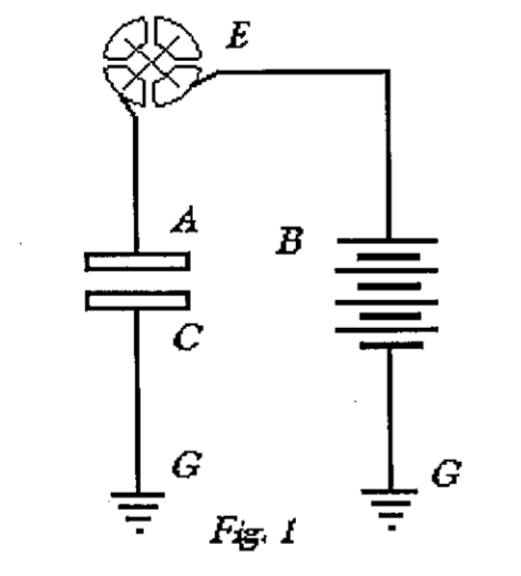
It is with these weaker energies that we are interested. The apparatus proposed by Abrams for use in obtaining the electronic reflex is a modification of the well-known ionizing apparatus. A good description of the latter may be found in "Electrons and Ionizing Radiations," Crowther, 1922. In the ionizing apparatus, there are two spaced plates, A and C, mounted in an ionization chamber, see Fig. 1. One plate is connected to the ground G and the other plate is connected through am electro-meter E and an electric battery B to the ground G.
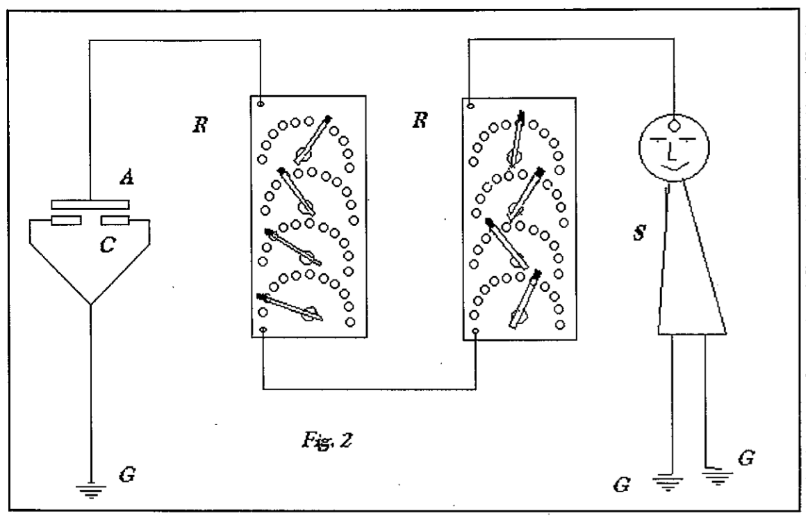
In the Abrams modification of this apparatus, Fig. 2, his Dynamizer resembles very closely the ionization chamber mentioned above. The lower plates of C of the Dynamizer are connected to the ground as in the older apparatus. The upper plate A is connected to the tuning device R and the latter connected to the subject, the person on whom the reflex is produced, to the ground G. By comparing these circuits outlined in Figs. 1 and 2, the close resemblance will be obvious.
The specimen for examination is placed between the plates of the ionization chamber in the older apparatus just as the specimen is placed between the plates of the Dynamizer. It was found that the electro-meter was not sufficiently sensitive to indicate the weak energies coming from all substances but the very few called radioactive; consequently the human reflex was substituted for the electro-meter of the older device. A tuning device was added to the circuit to make it selective. This permitted tuning the circuit to desired frequencies. The present improvement consists essentially in substituting the human reflex (reaction in the subject) for the electro-meter, eliminating the electric battery and adding a tuning device to make the circuit selective. The rest of both circuits are the same.
The use of a living tissue reflex as a detector for radiant energy of electromagnetic waves was discovered back in 1818 by the French physicist, Jean-Baptiste Biot, and long before such radiant energy was understood. Biot in his "Treatise on Experimental Physics and Mathematics" described how he produced this reflex in both live frogs and frog leg preparations as far as twelve meters away from operating static electrical machines. The use of the human reflex is only a development on Biot's early experiments.
The tuning quality of this device has been established by several independent observers. The oscillographic curves and a description of the apparatus employed by Colson in 1925 demonstrating this tuning effect is reported in the Journal of Electronic Medicine, Kirksville, Missouri, 1926. Demonstrations of these tuning characteristics in the Burnett Timken Laboratory at Alpine, New Jersey, is reported in the A.E.R.A. Journal, December, 1925. Mr. F. M. Henry demonstrated this tuning with apparatus at the A.E.R.A. Convention at Chicago, Illinois, September, 1929. Dr. W. E. Boyd of Glasgow, Scotland, has demonstrated with oscillographic curves, and mention of his results may be found in the British Homeopathic Journal, 1931.
Unfortunately, the settings of his tuning device were spoken of in such a way the impression was gotten that these settings represented corresponding amounts of resistance in ohms. Despite the same published result found by each of the above mentioned observers working independently, there are some who still persist in the thought that resistance in some manner effects tuning the apparatus to make it selective to desired frequencies. Some have carried this false notion so far that resistances of almost every conceivable form have been proposed in testing sets, and in amounts limited only by the proponent's imagination.
It is needless to say that resistance in this circuit acts just the same as in any high frequency electrical circuit, [74] and retards the flow of energy. The circuit can tolerate small amounts, but if used in much less amounts than have sometimes been proposed, would completely block the flow of energy. The operation of resistance, per se, in this apparatus might be likened to the wheel and axle of a wagon. It is always present, but due to the other characteristics of the wagon the latter is an efficient implement in spite of this friction.
While this apparatus is a modification of the ionizing apparatus in construction, its operation is entirely different. The operation of the ionizing apparatus depends on a radiant energy strong enough to split electrons from the atoms of air between the plates in the ionization chamber. The top plate is made strongly positive and the bottom plate strongly negative by the electric battery. The electrons freed between the plates by energy from the radioactive material are attracted to the positive plate because they are negative in character. These electrons act something like small switches, each one binding the gap between the plates A and C, Fig. 1, to permit the flow of a tiny current through the electro-meter. The amount of movement of the electro-meter pointer depends on the number of electrons engaging the positive plate in a unit of time. The electronic apparatus utilizes radiant energies that are very much too weak to split electrons from the air particles between the plates of the Dynamizer in the same manner that the energy emerges from the specimen in the ionization circuit. However no battery is used in the electronic device and the energy is caused to enter the circuit by tuning the latter to a harmonic of the energy.
One may cause an electrical current to flow through a conductor by directly connecting the conductor to a source of electricity, so that the conductor and source of electricity form a path or circuit. The current traverses this circuit much the same way as water passes through a circulating pipe system connected to a water pump. An electrical current, as referred to, may be either direct or slowly alternating in character. An example of such a circuit might be a electrical light system and its power supply, an electric bell and it’s battery, or the ionization device with it's special plates, traveling electrons, battery and electro-meter referred to above.
In each of the examples just mentioned, the source of electricity is connected directly to the conductor circuit and the current introduced into the latter by conduction. Another method for providing an electrical current in a circuit is by bringing the latter into the field of an oscillatory energy. A current will flow in the circuit when the natural frequency rate of the latter is the same or a close harmonic of the energy. The natural frequency rate of a circuit is very largely controlled by the inductance and capacitance in such circuit. This inductance is largely due to coils and the capacity due to condensers in the circuit. Whenever the values of the inductance or capacity, or any combination of them is changed the natural frequency rate of the circuit is correspondingly changed. This changing of the values of inductance and capacitance is called tuning. Where a current is introduced into a conductor by conduction, tuning is of little or no consequence, but where an oscillatory energy causes the current the tuning is all-important.
A good example of this sort of oscillatory energy causing a current is the well known radio receiving instrument and energy from a broadcasting station. The oscillatory energy from a broadcasting station causes a current to be set up in the radio receiving instrument when the latter is in tune with the frequency of the broadcast energy. The electronic testing instrument operates in the same manner. The energies from the diseased tissue have different frequencies and the testing instrument is provided with tuning means to tune it to receive these different frequencies in a manner similar to tuning the radio receiving instrument to receive the energies from different broadcasting stations. The values of inductance and capacitance effects in the electronic testing device are very small compared with those in the radio instrument because of the higher frequencies encountered in electronic work.
Tuning a circuit simply refers to changing its natural frequency by changing it's inductance or capacitance, or either of them, until it has the natural frequency of a desired vibratory energy, whether it be a [75] radio signal or the energy from a specimen in an electronic test. When a circuit is brought into tune with a desired oscillating energy, the latter can traverse the circuit and the circuit is said to be in resonance with the energy.
If the natural frequency of the circuit is not in tune or resonance with the energy, the latter cannot cause a current to travel in the circuit. This feature permits one to tune a circuit to a desired frequency and prevent all other frequencies from interfering with the detection of the desired one. This is why one can tune into and receive the broadcasting from one station and other broadcasting will not interfere. Also this is why one can tune into and detect the energy of a certain frequency from a tubercular lesion, for instance, without the energy from some other lesion and frequency that might be present interfering with discovering the presence of the tubercular lesion. Electronic testing consists of first tuning the device to the frequency of the one energy from the specimen and eliciting the electronic reflex to ascertain the presence or absence of one kind of lesion or a functional activity. Next, proceeding in exactly the same manner by tuning to another frequency of the energy coming from the specimen and eliciting the electronic reflex again. This is continued until all the "rates" in the gamut have been looked for, together with any special energy frequencies have been tested for.
The reflex caused by these various frequencies from the specimen is not always evidenced at the same area on the subject, but the energy at some frequencies cause the reflex to appear in other areas. Also, the same frequency will cause the reflex to appear in one or more distinct areas as will be explained later.
The electronic response may be elicited in several ways. It may be evidenced by percussing over the reflex area and is noted by a change in pitch or tone. A rod of suitable material will show an increased drag on this reflex area when drawn lightly over this area. Dr. Abrams preferred to use the percussion method, but often used the rod. In 1923, and a few months before his death, he discovered the conductivity of the skin to a small electrical current from a battery or some other source in the reflex area was increased. He provided the Amplistaphone to demonstrate this increased flow of current which is due to a lowering of the resistance in the skin as a result of a reflex caused by the action of the electronic energy. This instrument indicated the increased flow of current on an electric meter and also by means of headphones. In 1931, Mr. F.J. Hart of San Jose, California, greatly improved this instrument by using greater amplification of the current flow and in refinements in the device, substituting a loud speaker and a neon lamp for the earphones.
In Physico-Clinical Medicine, Vol. 5, 1921, directions are given for demonstrating that the skin in the reflex areas under the influence of the electronic energy shows a slight elevation in temperature in contrast with the adjacent skin. In 1930, Dr. J.C. Burnett of Alpine, New Jersey, improved on this means by using a delicate thermocouple and an electric meter for demonstrating the phenomenon.
Introduction to Electronic Therapy
by Thomas Colson, D.O., B.S., LL.B.,
San Francisco, 1936.
Contents
- History and Development
- Theory and Physics
- Definition & Description of Reactions
- The Testing Apparatus
- Obtaining the Reaction
- Localizing Reactions
- The Gamut
- Interpreting Reactions
- Treatment Apparatus
- Brief Outline of Course
Available through BSRF:
#B0049, "Introduction to Electronic Therapy"
References
- Colson, Thomas. Introduction to Electronic Therapy. San Francisco: College of Electronic Medicine. 1936. Print. [Available in BSRF xerographic format: #B0049, "Introduction to Electronic Therapy".]
- Rutherford, Ernest. Radioactive Substances and Their Radiations. Cambridge: Cambridge University Press, 1913. Print. <http://catalog.hathitrust.org/Record/001484716>
- Crowther, James A. Ions, Electrons, and Ionizing Radiations. New York: Longmans, Green & Co, 1922. Print. <http://catalog.hathitrust.org/Record/001482377>
- Biot, Jean-Baptiste. Traité De Physique Expérimentale Et Mathématique. Paris: Deterville, 1816. Print. <http://catalog.hathitrust.org/Record/009647770>
- Physico-Clinical Medicine. Vol. 5. San Francisco: College of Electronic Medicine, Blanche and Jeanne R. Abrams Memorial Foundation. 1921. Print. <http://catalog.hathitrust.org/Record/000066199>