

Magnetometers
FOR INVESTIGATING
UFO's AND OTHER
MAGNETIC
PHENOMENA
by L. GEORGE LAWRENCE
A variety of home-built detectors to indicate magnetic disturbances such as those reported to accompany UFO sightings.
OVER the past 30 years, thousands of UFO sightings have been reported to and investigated by government and scientific researchers. Most have been readily attributed to such things as aircraft, the planets, meteors, and luminescent swamp gas. A small but significant number of incidents remain unexplained. The possible extraterrestrial nature of UFO's therefore is still an open question.
Common to many reported UFO incidents are magnetic disturbances which affect compasses, auto speedometers, electric power meters, etc. Presented in this article are various types of sensing circuits which will detect such magnetic anomalies. The circuits are inexpensive to build and use readily available parts and materials. Their use, however, is not limited to amateur UFO investigations. These magnetometers will be of interest to anyone who wants to explore magnetic phenomena, and — students take note — make fine Science Fair projects.
All the magnetic-detection systems presented here employ audio and/or visual intrusion alarms.
Home Magnetometers. Although professionals monitor magnetic fields with such sophisticated devices as proton free-precession magnetometers, good results can be obtained using the inexpensive home-built magnetometers described here. These devices have low power consumption and can be battery-powered for lengthy periods. Although they have less sensitivity than the proton magnetometer, which measures the precession (wobble) of protons in the presence of a magnetic field, the inertia-less CRT and electro-induction magnetometers are faster by a factor of about 1,000.
- A1 — Electronic alarm (Mallory Sonalert © No. S-628 or similar)
- B1, B2 — 9-volt transistor battery
- C2 — 1000-μF, 15-volt electrolytic
- C3 — 10-μF, 15-volt electrolytic
- I1 — No. 1815 lamp (14 volts, .2 amperes, T-3¼ configuration)
- J1 — Four-contact male connector (Amphenol No. 91-859 or similar)
- K1 — 12-volt, 250-ohm spdt relay
- L1 — 10,000-ohm, ¼" inner-diameter reed relay coil
- L2 — See text
- M1 — 1-mA meter (Calectro No. D1-912 or similar)
- P1 — Four-contact female connector to mate with 11 (Amphenol No. 91-458 or similar)
- Q1 — HEP S9100 Darlington transistor (Motorola)
- R1 — 1.2 megohms
- R4 — 330 ohms
- R5 — 820 ohms
- R6, R9 — 100 ohms
- R8 — 3900 ohms
- R10 — 41-ohm, 4-watt resistor
- R2 — 50,000-ohm linear-taper potentiometer
- R3 — 10,000-ohm linear-taper potentiometer
- R7 — 10,000-ohm linear-taper, screwdriver adjustable potentiometer
- S1 — Spst normally open pushbutton switch
- S2 — Spst normally closed pushbutton switch
- S3 — Spst switch (part of R2)
- SCR1 — HEP RI001 silicon controlled rectifer (or any 200-μA gate-current SCR)
- Misc. — 2' (61-cm) x 3/16" (4.8-mm) mu-metal or soft iron rod; miniature test magnet; PVC plastic tube with plastic terminal containers; aluminum or brass hardware; suitable enclosure; wall feedthrough; cement for mounting L1 9-volt dc line-powered supply; etc.
PARTS LIST FOR FIG. 1
The following are ½-watt, 10% tolerance resistors:
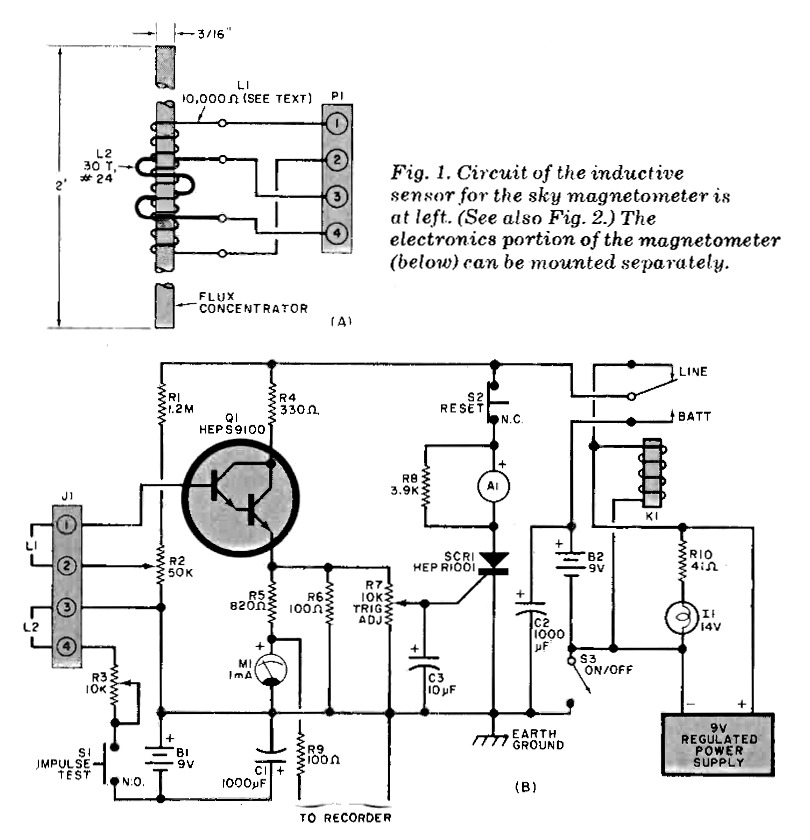
Sky Magnetometer. Shown in Fig. 1 is a field-induction magnetometer designed to have its sensor mounted on the exterior of a building. Two separate detection principles are employed. The high-speed sensor, shown schematically in Fig. 1A and photographically in Fig. 2, is of the electromagnetic induction type. The actual sensor is comprised of a 2' (61-cm) long mu-metal (a soft iron alloy) bar that serves as a flux concentrator for the coils. The larger of the two coils (L1) is a 10,000-ohm coil slipped over the bar and positioned at its center. Inductor L2 consists of 30 turns of No. 24 enamelled wire wound over the main coil. Coil L2 is used to induce a voltage across L1 for testing.
Signals induced across L1 are amplified by emitter follower Q1 (Fig. 1B).
(Transistor Q1 is a Darlington pair with a beta of at least 12,000.)
When IMPULSE TEST switch S1 is depressed, capacitor C1 discharges through potentiometer R3 and coil L2, inducing a current pulse in main sensing coil L1. Potentiometer R2 is used to adjust the sensitivity threshold. The amplified current pulse is indicated on meter M1 and can be passed to a paper chart recorder via resistor R9.
The current pulse at the emitter of Q1 is also passed via TRIGGER LEVEL Control R7 to the gate of SCR1. When SCR1 fires, it activates alarm A1. Because the power source is dc, A1 will remain on even after the triggering signal has passed. Normally closed RESET push-button switch S2 must be momentarily depressed to silence the alarm.
Operating power is obtained from a conventional line-operated regulated 9-volt dc supply. If line power should fail, relay K1 automatically switches to B2, a back-up battery supply.
TRIGGER ADJUST control R7 should be set to prevent the alarm from being triggered during lightning storms. Meter M1 is not critical, but it should be able to indicate the triggering threshold for the SCR, which is about 0.8 mA. A superimposed current of about 50 μA, the output of L1 amplified by Q1, will trigger the magnetometer. Near-trigger conditions can be observed on the meter, providing a built-in test facility in addition to L2.
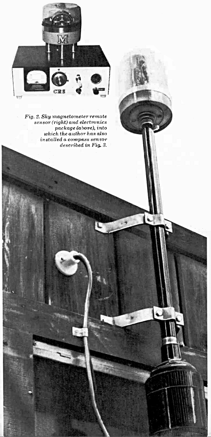
The instrument's construction and packaging, including the external sensor shown in Fig. 2, are not critical. The flux concentrator and coils can be protected from the elements by a length of magnetically neutral PVC plastic pipe, supported by aluminum brackets. The upper part of the sensor is enclosed in a glass or plastic container which can house another (optional) sensing coil made from an automotive ignition coil with its metal shield removed to provide full magnetic exposure.
The lower end of the pipe contains the electrical connections to the coils and is also protected by a glass or plastic enclosure. Connections between the coils and electronics console are made via shielded cables that pass through the support structure. Ground the cable shields to a true earth ground to avoid the danger of lightning strikes.
- IC1 — LM311 voltage-comparator integrated circuit (National)
- K1 — Spdt relay with 250-ohm or greater coil resistance
- OC1 — GE H13B1 optoelectronic coupler (Poly-Paks No. 92CU 2784, 2 for $1.19)
- R1 — 5000-ohm screwdriver-adjustable wire-wound potentiometer
- R2 — 150 ohms
- R3, R4, R5 — 10,000 ohms
- R6 — 100,000 ohms
- R7 — 2200 ohms
- Misc. — 6" (15.2-cm) compass needle with agate bearings and support stand (No. A2-1871 for $10.50 plus $1.00 postage from Sargent-Welch Scientific Co., 7300 N. Linder Ave., Skokie, IL 60076); nonmagnet housing with cover; aluminum or brass hardware; two stiff paper extensions; suitable enclosure for electronics package; hookup wire; solder; etc.
PARTS LIST FOR FIG. 3
The following are ½-watt, 10% tolerance resistors:
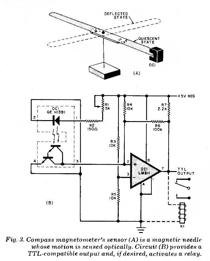
Compass Magnetometer. The second sensing system comprises a compass needle assembly and a geared compass of the automotive or marine type and is used for detecting slow magnetic field variations.
The compass needle assembly is shown in Fig. 3A. The primary sensor is a 6" (15.2-cm) magnetic needle mounted on a low-friction agate bearing. Two equally balanced opaque paper extensions are attached to the needle.
Once the magnetic needle settles down to a stable state, optical coupler OC1 must be positioned so that one of the opaque paper extensions fits into the narrow gap of the module. This module consists of a LED and a Darlington phototransistor, the two separated by a narrow gap into which the opaque paper extension is fitted. When the paper is in the gap, the light path is interrupted. This approach affords contactless and friction-free sensing of the needle's motion, and can also be used with meter pointers, cursor devices, eddy-current disks and mechanical indicators.
As shown in Fig. 3B, potentiometer R1 and current-limiting resistor R2, determine the light output of the LED in the pickup assembly. Only a minimal amount of LED output is required. With the LED illuminating the photo-transistor, the potential between Q1 pins 3 and 4 is typically about one volt. Comparator IC1 is wired so that its output is high when the light path inside OC1 is blocked, and goes low when the motion of the magnetic needle moves to allow an uninterrupted light path. Since IC1 is powered by a 5-volt supply, its output is TTL compatible. If desired, the output from IC1 can be used to power a relay (K1). Because the voltage comparator used is limited to a 20-mA output, the coil resistance of the relay must be at least 250 ohms.
If desired, the compass needle can be mounted vertically so that it dips up and down in the presence of a magnetic anomaly or disturbance.

- A1 — Electronic alarm (Mallory Sonalert® or similiar)
- C1, C2 — 500-μF, 15-volt electrolytic
- C3 — 50-μF, 15-volt electrolytic
- CRT — Electrostatic cathode-ray tube
- D1, D2 — 1-ampere, 50-PIV diode (Motorola HEP R0050 or similar)
- D3 — 8.2-volt zener diode (Motorola HEP Z0217 or similar)
- I1 — No. 756 lamp (14-volt, 8.2-mA in T-3¼ configuration)
- K1 — 12-volt spdt relay
- LDRI — CdS light-dependent resistor with 100-ohm light and 5-megohm dark resistance (Radio Shack No. 276-116 or similar)
- Q1 — HEP F0010 n-channel FET (Motorola)
- Q2 — HEP S0011 npn transistor (Motorola)
- Q3 — HEP 50012 pnp transistor (Motorola)
- R1 — 1-megohm linear-taper screwdriver adjustable potentiometer
- R2, R3, R7, R11 — 1000 ohms
- R4, R6 — 6800 ohms
- R5, R9 — 330 ohms
- R8 — 4700 ohms
- R10 — 12 ohms
- R12 — 680 ohms
- S1 — Spst normally closed pushbutton switch
- SCR1 — HEP R1241 silicon controlled rectifier (Motorola)
- Misc. — Power sources for acceleration and filament voltages, brightness, focus and centering controls and high-voltage cables; aperture mask and opaque cup for LDR1; nonmagnetic mount for CRT; 12-volt power supply; suitable enclosure for electronics; machine hardware; hookup wire; etc.
PARTS LIST FOR FIG. 4
The following are ½-watt, 10% resistors:
CRT Detector. The inertialess cathode-ray tube instrument shown in Fig. 4 is an extremely sensitive, high-speed magnetometer. Professional CRT magnetometers can measure extremely weak magnetic fields. The sensitivity of these CRT detectors exceeds that of both nuclear and rubidium-vapor magnetometers by a factor of two to four. However, commercial CRT systems are very expensive. This forces the experimenter to fashion a home-brew CRT magnetometer such as that shown in Fig. 4. The display speed of this system is contingent only on the signal-transfer time of the electronics package.
The CRT can be obtained from an oscilloscope or similar instrument. It should be an electrostatic — not electro-magnetic — system. Because the CRT must be operated 30' (9.1m) or more from its parent housing, lengthy cables are required to deliver the filament, centering, focus, and high voltages.
Attached to the glass faceplate of the CRT is light-dependent resistor LDR1 and an opaque mask with a tiny aperture cut in it. The size of the aperture should be about the same diameter as the focused spot on the CRT screen. The photocell/aperture mask assembly should be secured to the center of the CRT's faceplate in an opaque retainer cup. Do not use a permanent cement when attaching this assembly to the CRT because it may have to be moved somewhat if a phosphor burn (dark spot) develops on the screen.
The CRT must be operated without any type of shielding and should be supported by a nonmagnetic structure. Use well-insulated cables for the various CRT operating potentials. Set the brightness to produce a relatively low intensity spot, and then focus the spot. Using the horizontal and vertical centering controls, position the spot directly in the hole in the aperture mask. You can tell when the spot is properly positioned with the aid of an ohmmeter. Connect the meter across the leads of the photocell and operate the centering controls. The photocell's resistance will be very low when the spot is properly positioned.
When LDR1 is illuminated, the circuit in Fig. 4B causes K1 to close, applying power to READY lamp I1. If for any reason the CRT's beam moves away from the small aperture, K1 will momentarily deenergize and extinguish I1. This triggers an alarm circuit composed of SCR1 (whose gate is protected by D3) and audible alarm A1. Even if the beam returns to the aperture in the mask, the alarm will continue to sound until RESET switch S1 is momentarily depressed to interrupt the dc path through SCR1. Diode D2 protects transistor Q3 from voltage transients generated by K1 during switching.
Excursions of the CRT's electron beam can easily be calibrated in terms of gauss by using a small calibrating permanent magnet of known field strength and a square-ruled paper interface or plastic grid on the CRT's screen.
With the beam intensity set low and the spot's focus adjusted, R1 can be used to control the system's sensitivity. The CRT sensor can be given some directionality by housing it in a steel container whose sky-facing side has been removed. If the CRT is mounted outdoors, use a nonmagnetic weather cover to protect the CRT and high-voltage cables from the elements. As is the case with proton-precession and field-induction magnetometers, the inertialess CRT instrument is a total-field magnetometer, rather than an incremental field device.

- B1 — 1.5-volt D cell
- C1 — 500-pF capacitor
- C2, C3, C4 — 0.5-μF, 50-volt capacitor
- C5 — 1000-μF, 15-volt electrolytic capacitor
- D1 — SK3016 (RCA) or similar diode
- K1 — Reed switch (Hamlin No. MRMF-2-206, ¾" size or similar) fitted with 600-ohm coil (COTO coil No. U-12 or similar)
- L1 — Induction coil (see text)
- Q1, Q2 — SK3004 (RCA) or similar transistor
- R1 — 200-ohm, 2-watt resistor
- R2, R3 — 4700 ohms
- R5 — 50,000 ohms
- R6, R7 — 8200 ohms
- R8 — 1000 ohms
- R4 — 5000-ohm linear-taper potentiometer
- S1 — Spst switch
- Misc. — Metal enclosure; shielded cable; insulated wire for L1; machine hardware; external audio system; hookup wire; solder; hardware, etc.
PARTS LIST FOR FIG. 5
The following are ½-watt, 10% tolerance resistors:
Ground-Loop Sensing System. The chopper-interrogated ground-loop approach shown in Fig. 5 can be used to augment a magnetometer setup. The inductor, typically consisting of two turns of insulated copper wire measuring from 2' to 200' (0.6 to 61m) in diameter, employs a 330-Hz chopper in which Q1 and Q2 operate as an a stable multivibrator.
The chopper converts dc or low-frequency ac signals induced across the loop by an airborne magnetic agent into a serrated ac signal train. The train can then be processed by conventional audio systems. The nulling circuit consisting of R1, R2, R3, and nulling potentiometer R4 sets the quiescent state of the detector. An optional alarm circuit, shown in the dotted box, can be connected to the output of the audio amplifier. Diode D2 provides the rectification required by the gate of SCR1. The magnitude of this gate signal is determined by the value of Rd.
Diode D1 "despikes" chopper coil K1, and C4 maintains the frequency stability of the multivibrator. The circuit should be housed in a small, earth-grounded metal enclosure. The loop can be wound around suitably spaced wooden pegs and connected to the circuit via claimed that electrically disabled speedometers have indicated high road speeds while the vehicle was stationary. Similarly, there have been reports that home power meters exhibit sudden bursts of high speed without any increase in energy consumption.
Shown in Fig. 6 is an instrument that can detect anomalous eddy currents. The heart of the device, shown in A, is an aluminum disk that rotates above an shielded cable. If the loop is installed indoors, it should be mounted against a ceiling. Alternatively, it can be mounted on the roof.

- C1 — μF capacitor
- C2 — 1000-μF, 15-volt electrolytic
- C3 — 500-pF ceramic capacitor
- DI, D2 — HEP R0050 (Motorola) or similar diode
- I1 — No. 1815 lamp (14 volts, 0.2 amperes, T-3¼ size)
- IC1 — HEP C4020P (Motorola) dual-D flip-flop
- K1 — Spdt relay with 250-ohm or greater coil resistance
- LDR1 — CdS light-dependent resistor with 50,000:1 dark-to-light resistance ratio (Radio Shack No. 276-116 or similar)
- M01 — Converted power meter eddy-disk assembly (see text)
- QI — Transistor (Motorola HEP 50038 or similar)
- RI — 200-ohm, 5-watt variable resistor
- R2 — 10-megohm linear-taper screwdriver adjustable potentiometer
- R3, R4 — 5.1-megohm, ½-watt resistor
- R5 — 27-ohm, ½-watt, 10% tolerance resistor
- Misc. — Iron-core (mu-metal) form; No. 10 insulated wire; copper tubing; brake magnet; opaque light tubes; protective covers; machine hardware; hookup wire; etc
PARTS LIST FOR FIG. 6
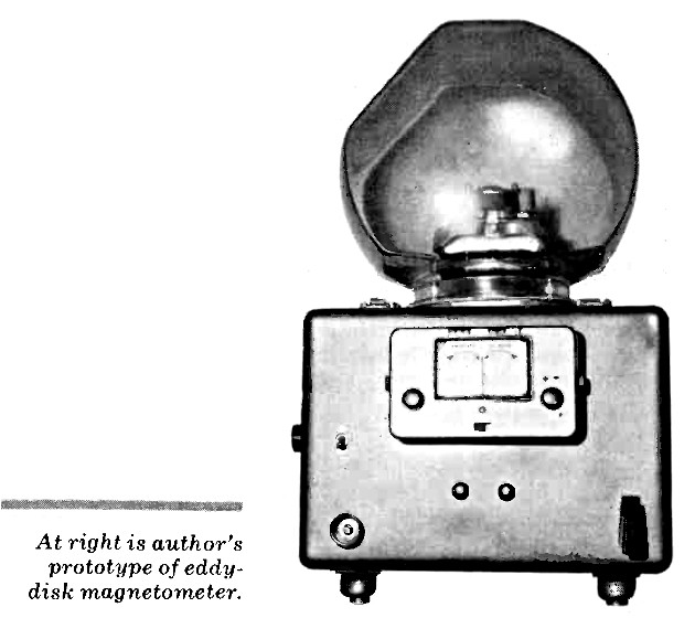
Eddy-Disk Magnetometer. According to some sources, one presently unexplained phenomenon influences the behavior of eddy-disk devices like those in automotive speedometers and domestic power meters. It has been iron-core coil containing 15 turns of 3/32" (2.38-mm) wire connected to a pair of receptor stubs formed from 0.25" (6.35-mm) diameter copper tubing. A small, thin iron "flag" that opposes a relatively weak permanent magnet provides a force sufficient to prevent the disk from rotating under unenergized conditions. The overall design resembles that of a standard home power meter. The permanent magnet used for the brake should be positioned near the flag so that the disk is stationary under ambient conditions.
The motion of the disk is detected by optical means (see Fig. 6A). Exciter lamp I1 generates a luminous output which passes through a small aperture in the disk. Light passing through the aperture falls on LDR1 on the other side of the disk. The light path should be confined to the aperture in the disk. A small opaque tube can be used on either side of the disk to confine the light. These tubes will keep the light emitted by I1 from spilling over the edge of the disk and possibly biasing LDR1. The tubes should not contact the disk surface.
As shown in Fig. 6B, LDR1 triggers monostable multivibrator IC1A which clocks flip-flop 1C1B on and off as the disk rotates. Two outputs are provided. One, at the emitter of Q1, can be changed in level to produce a TTL-compatible output for driving conventional decade counters. The other output is via relay K1, which can be used to activate a mechanical counter or an alarm.
Potentiometer R2 allows the experimenter to adjust the sensitivity of the sensing circuitry. Because of Q1's limited current-handling ability, the coil resistance of K1 must be at least 250 ohms. Control R1 provides a means for adjusting the intensity of L1.
To keep out any extraneous light, a nonmagnetic, opaque cover can be mounted over the disk, L1, and the I1/LDR1 assembly. A larger nonmagnetic (glass or plastic) dome is recommended to safeguard the package against moisture and air currents. The receptor stubs can be mounted outside the package.
In Closing. The various home magnetometers that have been presented in this article should be operated as far away as possible from any contaminating magnetic fields produced by electrical machines, permanent magnets, etc. They should also be housed in nonmagnetic structures. Armed with these detectors and scientific curiosity, you will be well equipped to investigate magnetic phenomena — whether they are produced by natural, man-made, or perhaps even extra-terrestrial causes.
Originally published in "Popular Electronics" (May 1978). Browse AmericanRadioHistory.com for complete issues of P.E. and many other historical radio and electrical publications in PDF format.
Return to the BIO-ICOMM Project homepage or the Bibliography of L. George Lawrence.